Oscilloscope DSO152 Mini Pocket Handheld Oscilloscope
Last Updated on August 16, 2024 by Engr. Shahzada Fahad
Table of Contents
Oscilloscope DSO152:
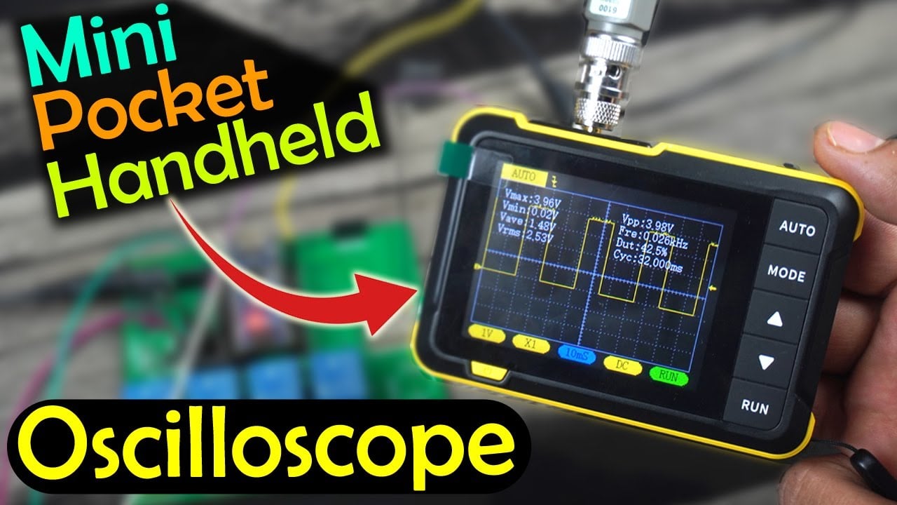
Oscilloscope DSO152 Mini Pocket Handheld Oscilloscope- a brand new Mini Pocket handheld oscilloscope the DSO152 by Fnirsi. DSO stands for Digital Storage Oscilloscope. So, it’s a digital oscilloscope that can measure and record electrical signals. It converts the analog signal into a digital format and stores it in its digital memory, allowing for easy recall and analysis.
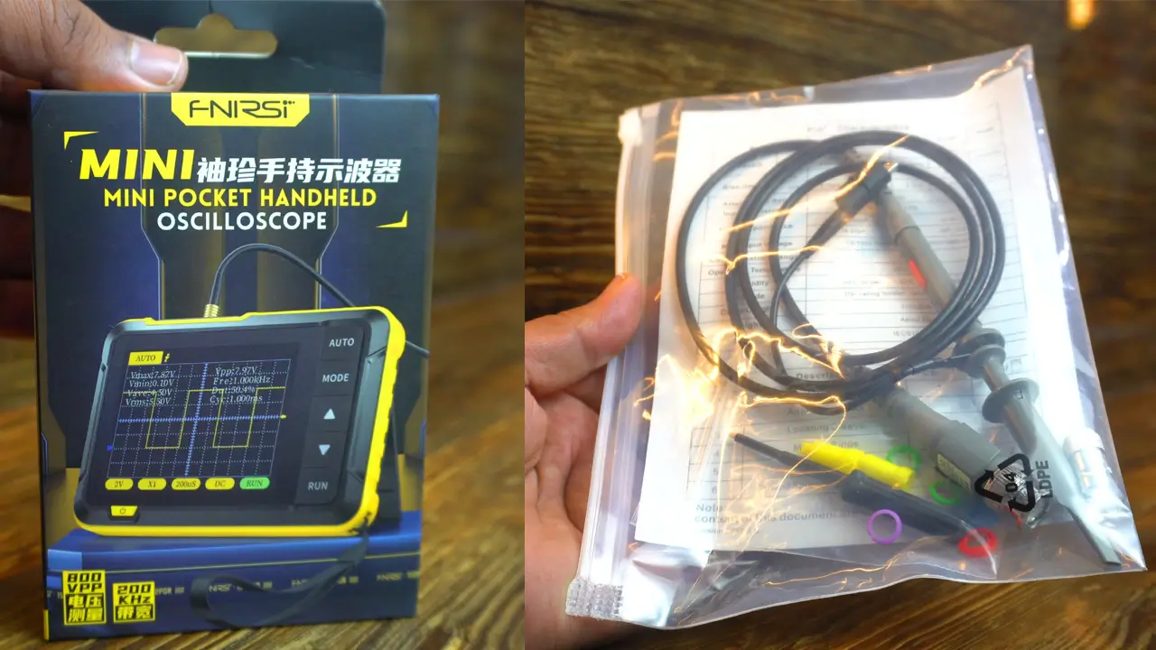
Along with this, you also get a Probe and a user guide. I will explain how to use this probe, but first let’s go ahead and unbox this Oscilloscope.
Product links:
| Product | Source | Source |
| Oscilloscope DSO152 | Amazon | AliExpress |
*Disclosure: These are affiliate links. As an Amazon Associate I earn from qualifying purchases.

It comes with an instructional manual, Alligator clip leads with a little connector that plugs into a slot given on top of the Oscilloscope, a USB type C Cable for the charging, and a strap.

DSO152 is a highly practical and cost-effective handheld Oscilloscope launched by Fnirsi, which is aimed at the maintenance industry and the research education industry. The Oscilloscope has a real-time sampling rate of 2.5MS/s, a bandwidth of 200KHz, and complete trigger functions (single, normal, and automatic). It can be used freely for both periodic analog signals and non-periodic digital signals, and can measure voltages up to ±400V.
We will also measure PWM signals with this oscilloscope. To generate PWM signals, we will use Arduino. So, you can also use this oscilloscope to test your Arduino projects.
Furthermore, we will also measure an analog sensor with this oscilloscope, and we will check the charging and discharging time of the RC circuit. So, be sure to watch the complete video for a full review and testing. Link to the video is given at the end of this article.
The screen is 2.8-inch 320×240 resolution high-definition LCD screen.
It has a built-in 1000mAh high-quality lithium battery, that can be used continuously for about 4 hours after fully charged.

On the left side, you can find the reset hole, charging indicator light, during the charging its Red and when the battery is fully charged then the green LED is turned ON. And below the charging indicator led you can find the Type-C charging interface (5V/1A).
On the top, you can find the Signal input probe (MXC) interface, next to it you can find an interface for the Square Wave Calibration, and there is also a trackwheel button; it serves multiple purposes. Short press left or right to scroll through different parameters function selection. And if you short press this button; it will exit the auto calibration.
There is nothing on the right side.
The AUTO button is used for the Automatic adjustment.
The MODE button also serves multiple purposes. If you short press the Auto button you can select AUTO, Single, and Normal switching. And if you long press this button you can switch between the Rising edge or falling edge switching.
The up and down arrows are used for the Parameter addition and subtraction adjustment.
Run button also serves multiple purposes. Short press this button to Run/Pause waveforms. If you long press this button it will show or hide the detailed parameters.
On the front; below the screen you can also see a power switch button, simply long press this button to turn on the display. To turn it off simply short press this button.

So this is the Probe that we will be using for the measurements and you can see it has a standard BNC Connector and in order to use it with the Oscilloscope it’s also provided with a connector and without it, you won’t be able to connect this Probe to the Oscilloscope, because it has a different type of interface. So, first you will need to connect this and then you can plug it in.
The Probe also has a compensation trimmer which is used for the frequency compensation adjustment in 10X mode.
The probe has a Retractable hook tip and the ground lead. Use the alligator clip to attach the probe to a ground reference.
The probe also has a Slide Switch, it is used to set the probe attenuation.
So, that’s all about the accessories and interfaces.
For the practical demonstration; watch the video tutorial. In the video, I have explained; how to use buttons, how to measure an analog signal, how to check the charging cycle of an RC circuit, and how to measure a PWM signal from the Arduino.
Watch Video Tutorial:
Discover more from Electronic Clinic
Subscribe to get the latest posts sent to your email.