PLC Lab Exercise Logic Gates, PLC Ladder Logic Diagram Examples
Last Updated on February 25, 2024 by Engr. Shahzada Fahad
Table of Contents
Description:
PLC Lab Exercise Logic Gates – If you are a student of Electrical, Electronics, or Software engineering, etc, then you probably know about the importance of Logic gates and that’s the reason you are here because you want to learn more about the Logic gates and how these Logic Gates are implemented in the PLC ladder logic diagram/programming whatever you call this.
We know from the books we studied “Logic Gate is building block for Digital Circuit”. A logic gate takes Binary Input in the form of 0 or 1 and gives a Binary Output based on the Input provided; the output of the Logic Gate is also in the form of 0 or 1. Due to its importance logic gates are most frequently used in the PLC ladder logic programming, and that’s the reason when you start learning the PLC Ladder logic programming, the first thing that you are introduced to is the Logic Gates.
This is the PLC Lab Exercise Logic Gates tutorial, which explains how to use the most basic Logic Gates in the PLC Ladder logic programming. For this PLC Lab Exercise Logic Gates, you don’t need to purchase a PLC. We will use be using the WinProLadder PLC ladder logic programming Software. In this software, we can write our ladder logic programs and we can also run simulations. I have a separate Tutorial on; how to use the WinProLadder Software and covered all the basics like for example how to start a new project, how to select a PLC model, how to use comments, how to write your first PLC program, and what is the best PLC for the beginners. So I highly recommend you should read this article and then you can resume from here.
In today’s Tutorial which is based on the “PLC Lab Exercise Logic Gates”, I am only going to explain the Logic Gates and how they are used in Ladder Logic Programming. In this tutorial, we will cover the following gates
- NOT Gate
- AND Gate
- NAND Gate
- OR Gate
- Nor Gate
- Exclusive- XOR Gate
- Exclusive- XNOR Gate
Without any Further Delay, let’s get started!!!
Amazon Links:
Fatek PLC, FBs-14MAR2-AC (FBs-14MA):
IR adjustable infrared Proximity Sensor 2v to 24V:
Other Tools and Components:
Super Starter kit for Beginners
PCB small portable drill machines
DISCLAIMER:
Please Note: these are affiliate links. I may make a commission if you buy the components through these links. I would appreciate your support in this way!
Note:
Before I explain how these Logic Gates will be used in the PLC Ladder Logic programming, first I would like to tell you, that these Ladder Logic Programs will be written for the Fatek PLC FBs-14.
I will use Inputs: X0, X1, X2, … Xn and
Outputs: Y0, Y1, Y2, … Yn.
NOT Gate:
A NOT Gate is usually known as the inverter or Buffer is a logic gate that implements logical negation, in simple words the NOT Gate is used to convert 1 into 0 and similarly 0 into 1. The NOT Gate takes only 1 input and gives only one output.
NOT Gate Symbol:

NOT Gate Truth Table:

When the input is zero the output is 1, while when the input is 1 then the output is 0.
NOT Gate PLC Ladder Logic Diagram:
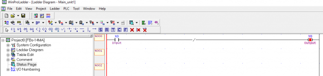
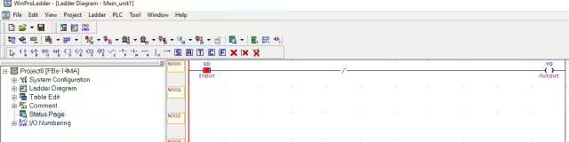
This is how a NOT Gate is implemented in the Ladder Logic programming. As you can see in the pictures above when there is no input the output Y0 is high, while for high input we have low output at Y0.
AND Gate
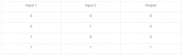
The AND Gate has two inputs (input 1 and Input 2) and one Output. The output of the AND Gate is high when both the inputs are high. The output is low when any of the inputs are low. This can be clearly understood from the truth table given below.
AND Gate Symbol:

AND Gate Truth Table:
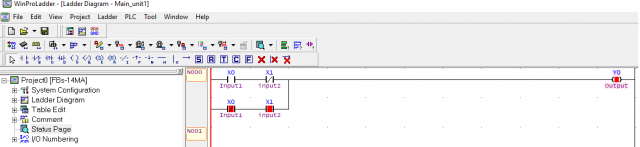
AND Gate PLC Ladder Logic Diagram:
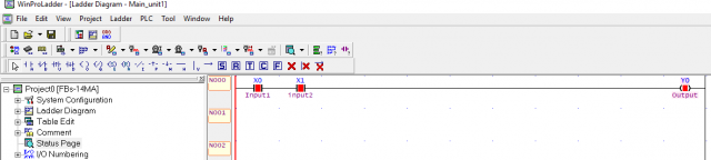
As you can see two normally open type contacts are used. When both the inputs are high the output Y0 is high. The output is low only when any of the inputs are low. So for the output to remain ON both the inputs should be high.
NAND Gate
The NAND Gate is the inverse of the AND Gate. The NAND Gate takes two inputs and gives only one output just like the AND Gate.
NAND Gate Symbol:

NAND Gate Truth Table:

NAND Gate PLC Ladder Logic Diagram:
As you can see how easy it is to implement the NAND Gate, we just put the inverse and that’s it. You can see the output of the NAND Gate is just the opposite of the AND Gate. If any of the inputs is low the output is high. The output is low only if both the inputs are high.
OR Gate
Unlike the AND Gate, the OR Gate also has two inputs “input1 and input2” and has only 1 output. The output of the OR Gate is high if any of the inputs is HIGH. The output is low when both the inputs are low.
OR Gate Symbol:

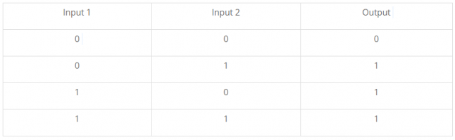
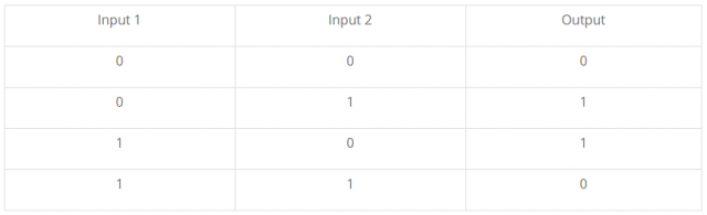
OR Gate Truth Table:
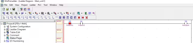
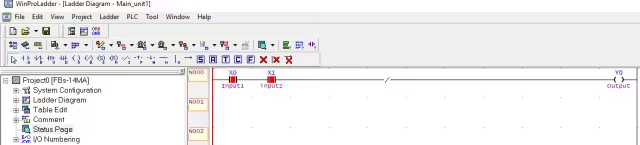
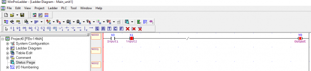
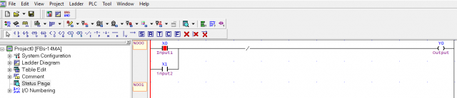
OR Gate PLC Ladder Logic Diagram:

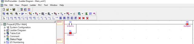
The OR Gate is implemented by connecting the inputs in parallel. As you can see in the pictures above, the output is off when both the inputs are low. While in the second picture you can see the output Y0 is high as the input2 is high. So, for the OR Gate if any of the inputs are high the output will remain ON.
NOR Gate
The NOR Gate is just the inverse of the OR Gate. The output of the NOR gate is opposite to OR Gate. The output of the NOR Gate is high if both the inputs are low and the output is low if any of the inputs are high or both the inputs are high.
NOR Gate Symbol:

NOR Gate Truth Table:

NOR Gate PLC Ladder Logic Diagram:

As the NOR Gate is the Inverse of the OR Gate, so this Gate can be implemented by only putting the Inverse sign after the OR Gate. As you can see when both the inputs are low the output is high and when any of the input is high then the output is low.
Exclusive- XOR Gate
The output of the XOR Gate is low for similar inputs while for the dissimilar inputs the output is high. Let’s say if you have two high input or two low inputs the output remains low. So for similar inputs, the output is low, while for different inputs the output is high.
XOR Gate Symbol:

XOR Gate Truth Table:
XOR Gate PLC Ladder Logic Diagram:

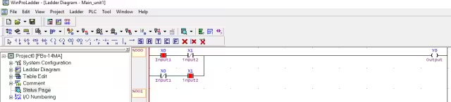
As you can see for the similar inputs the output is low, while for the dissimilar inputs the output is high. This looks a bit complex but trust me it’s really easy after you make the same Ladder logic diagram in the WinProLadder software you will understand how this actually works. You can see the X0 and X1 are used in series and they are also used in parallel.
Exclusive- XNOR Gate
XNOR Gate Symbol:

XNOR Gate Truth Table:
XNOR Gate PLC Ladder Logic Diagram:
I hope that now you have an idea of how the logic gates are used in the PLC Ladder logic Programming. I am leaving the XNOR Gate Truth Table and the XNOR Gate PLC Ladder Logic Diagram as an assignment for you. Let me know in the comment the output of the XNOR gate.
For more PLC and SCADA based projects subscribe to my Website. You will get a notification email, each time I upload a new article. If you have any question let me know in a comment.
Related Projects:
https://www.electroniclinic.com/logic-gates-in-digital-electronics-complete-guide/
https://www.electroniclinic.com/plc-and-scada-based-load-management-plc-scada-system/
https://www.electroniclinic.com/plc-ladder-logic-programming-examples-with-detailed-explanation/
Discover more from Electronic Clinic
Subscribe to get the latest posts sent to your email.


Hi can we use the informaton here to for educational purposes and we will not be liable by using the content. even if we cited you as the primarysource of information here? thanks 😀
yes, you can use it, but don’t forget to mention http://www.electroniclinic.com