TM1637 a 4 digit 7 Segment display with Arduino
Table of Contents
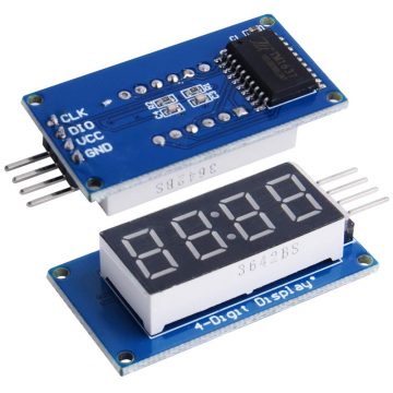
TM1637 Digital Display:
TM1637 Digital Display Module with Arduino– I have been using different types of LCDs and Oled display modules in different types of projects. I have also a very detailed getting started tutorials on how to use the 16×2 LCD and Oled display modules. These LCDs and Oled display modules are expensive as compared to the digital display modules like for example the Seven Segment modules which are available in common anode and common cathode configuration. The seven segment modules can be used in simple counter type projects, can also be used for the temperature display, etc. Multiplexing seven segment display may be very time consuming for beginners as we cannot display multiple digits on the single seven segment display. We have a readymade multiplexed seven segment display module the TM1637. In this tutorial we will discuss how to use the TM1637 digital display with an Arduino and NodeMCU ESP8266.
Amazon link:
Arduino Nano USB-C Type (Recommended)
*Please Note: These are affiliate links. I may make a commission if you buy the components through these links. I would appreciate your support in this way!
Specification of TM1637:
- 4 M2 screw holes for easy installation.
- 4-digit LED display module with LED brightness adjustable and clock point.
- Display device is a total of 4 red LED word tube. Digital tube 8 grayscale adjustable.
- The driver IC is TM1637; only two signal lines can make MCU control four Digit 8-segments LED can be used to display decimal, letters and so on.
- Display common anode for the four red LED
- Size:42X24X12mm
- Control interface: a total of 4 pins (GND, VCC, DIO, CLK), GND to ground, VCC for the power supply, DIO for the data input and output pins, CLK for the clock signal pin.
Interfacing TM1637 with the arduino:
So the first thing you want to do is connect the clock pin to any pin on the Arduino.
- I connected the clock pin of the TM1637 with the digital pin 3 of the arduno.
- Now connect the DIO pin of the TM1637 with digital pin 4 of the arduino.
- Now connect the VCC of the TM1637 with the 5V of the arduino.
- Connect the ground of the TM1637 with the ground of the arduino.
For now these connections are enough for you guys to get started with this amazing Seven Segment module. Let’s go ahead and write a very simple program.
TM1637 Arduino code:
|
1 2 3 4 5 6 7 8 9 10 11 12 13 14 15 16 17 18 19 20 21 22 |
#include <TM1637.h> int clk = 3; int dio = 4; TM1637 tm (clk,dio); void setup() { // put your setup code here, to run once: tm.init(); tm.set(3); } void loop() { // put your main code here, to run repeatedly: tm.display(0,1); tm.display(1,2); tm.point(1); tm.display(2,10); tm.display(3,11); } |
TM1637 Arduino Code explanation:
So now let’s work on the software the first thing you want to do is to install the TM1637 library.
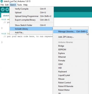
Or you can follow the instructions given below. So, to do that go to sketch include library and manage libraries.
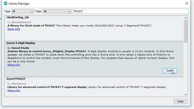
Now we will write TM1637 and pick the one that’s labeled Grove for digit display by seed studio and click install.
So once that’s installed you want to include the library by typing it in the code.
|
1 |
#include <TM1637.h> |
After this let’s make variables for our clock pin and DIO pin. So our clock pin was pin 3 and DIO was pin 4
|
1 2 3 |
int clk = 3; int dio = 4; |
After this let’s initialize our TM1637 objects and name it TM and you pass in it the clock pin data as your first parameter and a DIO pin data as a second parameter.
|
1 |
TM1637 tm (clk,dio); |
After this we have to initialize it
|
1 |
tm.init(); |
After that we have to set the brightness and we do that with TM dot set and then you pass in a brightness value from 0 to 7. In our case we have pass in the value 3 to set the brightness.
|
1 |
tm.set(3); |
So now we can actually make it display things so as an example let’s make a display 11 : ab. So to do that you just do TM dot display and you pass the two parameters the first is position where the first digit is 0 in the last digit is 3.
The second is character where when we write the number 0 to 9 it display the number and when we write the number from 10 to 15 display the letters A to F on the display. So to make it display 1 as our first character we simply do tm.display position 0 and 1 for the two tm.display 1 and 2 because the position is 1 and the character is two to make it display.
|
1 2 3 |
tm.display(0,1); tm.display(1,2); |
For the “:” sign we will write tm.point and then one where one turns on point and zero turns off the point.
|
1 |
tm.point(1); |
Then to display we will write the command tm.display 20 and 10 where 2 is for position which is the third position and 10 is the a character
|
1 |
tm.display(2,10); |
Now for B, tm.display 3 and 11 where three represents the 4th position and 11 is for the b character. tm.display(3,11);
After uploading code to the arduino we will see the display on the TM1637.
IOT based clock using TM1637:
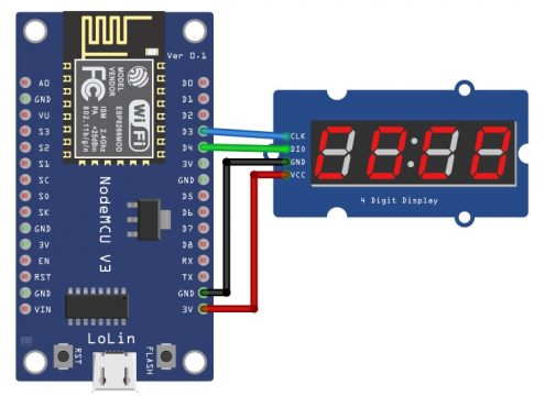
Now to make IOT based Clock we will use NodeMCU ESP8266 with TM1637. Now to interface the TM1637 with Nodemcu ESP8266 we will perform the following steps:
- Connect the clock pin of the TM1637 with the digital pin 3 of the Nodemcu.
- Now connect the DIO pin of the TM1637 with digital pin 4 of the Nodemcu
- Now connect the VCC of the TM1637 with the 3V of the Nodemcu
- Connect the ground of the TM1637 with the ground of the Nodemcu
IoT digital Clock Nodemcu ESP8266 Complete code:
|
1 2 3 4 5 6 7 8 9 10 11 12 13 14 15 16 17 18 19 20 21 22 23 24 25 26 27 28 29 30 31 32 33 34 35 36 37 38 39 40 41 42 43 44 45 46 47 48 49 50 51 52 53 |
#include <NTPClient.h> #include <ESP8266WiFi.h> #include <WiFiUdp.h> #include <TM1637Display.h> // #define CLK D3 // Define the connections pins: #define DIO D4 TM1637Display display = TM1637Display(CLK, DIO); // Create display object of type TM1637Display: const char *ssid = "electronic clinic"; const char *password = "123456"; const long utcOffsetInSeconds = 19802; // Define NTP Client to get time WiFiUDP ntpUDP; NTPClient timeClient(ntpUDP, "pool.ntp.org", utcOffsetInSeconds); void setup(){ Serial.begin(115200); // Clear the display: display.clear(); WiFi.begin(ssid, password); while ( WiFi.status() != WL_CONNECTED ) { delay ( 500 ); Serial.print ( "." ); } timeClient.begin(); } void loop() { int A,B; timeClient.update(); display.setBrightness(7); // Set the brightness: A = timeClient.getHours() * 100 + timeClient.getMinutes(); B = timeClient.getSeconds(); if((B % 2) == 0) { display.showNumberDecEx(A, 0b01000000 , false, 4, 0); } else { display.showNumberDecEx(A, 0b00000000 , false, 4, 0); } } |
IoT digital Clock Nodemcu ESP8266 Code Explanation:
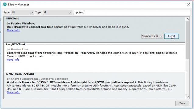
First of all we will include the NTPClient library which network time protocol and if we have access to the internet we can get and we do not require any hardware. This library will be used to get the time online. We will go to sketch and then go to manage library and write ntpclient and install it.
|
1 2 3 4 5 6 7 8 9 10 11 12 13 14 15 16 17 18 19 20 21 22 23 24 25 26 27 28 29 30 31 32 33 34 35 36 37 38 39 40 41 42 43 44 45 46 47 48 49 50 51 52 53 54 55 |
#include <NTPClient.h> #include <ESP8266WiFi.h> #include <WiFiUdp.h> Insert the TM1637 library which we give in the link #include <TM1637Display.h> // Now we will define the pins which are connected with the esp8266 #define CLK D3 // Define the connections pins: #define DIO D4 This command will update object TM1637Display display = TM1637Display(CLK, DIO); // Create display object of type TM1637Display: This command will be used to give the wifi name and password which will be used to connect with the esp8266. const char *ssid = "electronic clinic"; const char *password = "123456"; const long utcOffsetInSeconds = 19802; Now we will use this command to connect esp8266 with the User datagram protocol // Define NTP Client to get time WiFiUDP ntpUDP; A client will then transmit a request packet to a NTP server. In response to this request the NTP server sends stamp packet. A time stamp packet contains multiple information like UNIX timestamp, accuracy delay or time zone. A client can then parse out current date and time values. The pool.ntp.org will automatically picks time server which are geographically close for you. NTPClient timeClient(ntpUDP, "pool.ntp.org", utcOffsetInSeconds); void setup(){ Serial.begin(115200); // Clear the display: display.clear(); WiFi.begin(ssid, password); while ( WiFi.status() != WL_CONNECTED ) { delay ( 500 ); Serial.print ( "." ); } timeClient.begin(); } void loop() { int A,B; timeClient.update(); display.setBrightness(7); // Set the brightness: Now through this command we will store the hours and minutes in the variable A and B. A = timeClient.getHours() * 100 + timeClient.getMinutes(); B = timeClient.getSeconds(); These commands will be used to send data to the TM1637 if((B % 2) == 0) { display.showNumberDecEx(A, 0b01000000 , false, 4, 0); } else { display.showNumberDecEx(A, 0b00000000 , false, 4, 0); } } |
After uploading the code to the nodemcu ESP8266 the current time will be shown on the TM1637 Seven Segment display module.




HY16K33 to a sca60C and a adriino uno. Having trouble !!! Your circuits and discription are great