Transmission lines, Overhead Power lines & Underground power lines
Last Updated on December 14, 2020 by Engr. Shahzada Fahad
Table of Contents
Transmission lines:
The transmission system connects the renewable and conventional source with the regional and local distribution system from the distribution system through Power Lines( Overhead Power Lines or Underground Power Lines). The electricity is then delivered to the household overland. We know that power can be generated using different procedures and then distributed with the help of power lines or Transmission lines. The conventional procedures that are used in generation of power are:
- Thermal power plant
- Hydroelectric power plant
- Nuclear power plant
- Wind power plant
- Tidal power plant
- Magneto Hydro Dynamic Power Generation
Primary transmission:
When the power is generated at a power station like hydroelectric, thermal or nuclear power plant the electrical energy will typically be in range between 11kV and 33kV. This electrical energy is stepped up with the help of a step up transformer which will change this voltage in 220 KV, 132 KV or in 400 KV. Now this electrical energy will be transmitted with the help of transmission lines which is known as primary transmission. The voltage is step up in order to reduce the losses that occur when the power is transmitted. When the voltage is step up the current will reduce and the power will remain same. In the primary transmission the power is transmitted from the power station to the grid station or substation. The primary transmission is also known as high voltage transmission.
Secondary transmission
When electrical power reaches from the power station to the grid station or substation, the voltage is stepped down with the help of a step down transformer to a voltage typically between 33kV and 66kV. It is then sent to transmission lines emerging from this receiving station to electrical substations closer to “load centers” such as cities, villages, and urban areas, you can distribute the power lines using Overhead or Underground power lines . This process is known as secondary transmission. The secondary transmission is also known as low voltage transmission.
Distribution:
Primary distribution:
Now the 33 KV or 66 KV which are received from the secondary transmission are again step down with the help of transformer to 11 KV this process is known as primary distribution. These voltages are usually supplied to the factories, villages, cities etc. The primary distribution is also known as high voltage distribution.
Secondary distribution:
Now the 11 KV is step down to 220 V and transmitted to our homes where this power will be consumed. The secondary distribution is also known as low voltage distribution. In most of the Asian countries you will even see overhead power lines for the LV which looks very messy and dangerous. I personally spent a lot of time UAE and I didn’t see Overhead lines for the LV, the power lines are distributed using the underground power lines distribution system.
Now we will discuss different types of transmission.

Transmission according to the supply voltage:
There are two types of transmission according to the supply voltage which are:
- AC voltage
- DC voltage
There are further three types of ac voltages which are:
- Single phase voltage
- Two phase voltage
- Three phase voltage
Single phase voltage:
The single phase voltage has further three types:
- Single phase two wire system
- Single phase mid wire system
- Single phase three wire system
Two phase voltage:
Two phase voltage are of three types:
- Two phase two wire system
- Two phase mid wire system
- Two phase four wire system
Three phase voltage:
Three phase voltage are of two types:
- Three phase three wire system
- Three phase four wire system
Overhead transmission / Overhead Power lines:
In overhead distribution system we have electrical poles at a certain distance on which ASCR is placed through which electricity is distributed. The initial cost of overhead transmission system is less. The public safety of the overhead system is less. The faults in overhead system are less as compared to the underground transmission system. The flexibility of the overhead system is maximum as we can easily use another wire with it while in underground system we will create separate system or channels if we want to add another wire. The fault in overhead transmission system can be easily identified because the wires are visible while in the underground power lines distribution system we cannot easily identify the fault because the wires are not visible. Due which overhead system can easily be repair while difficulties occur in the underground system. The working voltage of the overhead system is up to 400 KV while the working voltage for the underground transmission is up to 66 KV due to insulation difficulties.
The overhead lines transmit high voltage electricity and only in special cases the voltage is transmitted through underground cables. One important element of overhead lines is the pylons. They carry the conductors the 50 Hz grid contains about 14000 pylons. Conductors have to be isolated from the earth pylon. They are therefore fixed with isolators normally the difference between 220 KV and 380 KV lines can be pin pointed by checking the number of isolator
- 220 KV lines frequently have 2
- 385 KV lines have 3 or isolators
The electricity is transported through conductors in form of small electrons with negative charge. Earth wires are attached to the top of the pylons they do not transport the electricity but protect the live conductors against the lightning strikes. The overhead lines of the 50 Hz high voltage grid are usually equipped with two electrical circuits. The power grid ensure uninterrupted and secure electricity supply if one system or even the entire line fails. This securing principle is called N-1. When 50 Hz supply decides to build new lines with respect to certain rules. We avoid residential areas wherever possible, bundle the lines with other infrastructure such as streets or railways and try to effect natural areas as little as possible. We compensate any environmental impact protecting human being, wild life and nature is our highest priority.
Underground transmission / Underground Power Lines:
In underground transmission system the wires are passed underground in pipes or some other means. The power is distributed with the help of insulated cables. The underground power lines distribution system is expensive than overhead power lines distribution system and is more reliable and safe than overhead power lines distribution system. The underground power lines transmission system is used in such where we want to pass power through roads. The appearance of the overhead system is not very good as compare to the underground transmission system. Because in the underground power lines distribution system the wires are not visible. The lightning effect of the overhead power lines system is maximum while in the underground power lines system the lightning effect is less. The underground transmission system has less interference with the transmission system while in the overhead system has maximum interference with the communication.
In the past power generating plants only local areas were served. Electricity did not have far to travel between where it was created and where it was used. As power plant grew larger and further away from populated areas, the need for ways to efficiently move electricity over long distances has become more and more important.

Generating electricity is a major endeavour, often a complex industrial process that requires huge on-going costs for operation and capital investments, fuel and maintenance. Electrical utilities only earn revenue on the power that makes it to the meter. They are not compensated for the energy lost on the grid. So if we are going to the trouble of producing electricity, we want to make sure that as much of it as possible actually reaches the customer for whom it is intended. Power plants are usually located away from populated areas for a variety of reasons. That means that massive amount of electricity need to be transported long distances from where it is created to where it is used. But if we want this transport to be efficient there is more to consider. Even good conductors like aluminium and copper have some resistance to the flow of electric current. We can see this at home we can measure small drop in voltage when a hair dryer is plugged directly in to an outlet and turned on. This difference in power represents energy lost as heat from the resistance of the extension board. In fact this lost power is pretty easy to calculate if we want to do it we will do a little algebra. As we know that electrical power is the product of current that is the flow of electric charge and voltage (that is the difference in electric potential). For a simple conductor we can use ohm law to show that the drop in voltage drop from one end of the wire to other is equal to the current times, the resistance of the wire measured in ohms. Substituting this relationship we find that the power loss is equal to the product of current squared and resistance.
P= IV
V= IR
P=I2R
So if we want to reduce the losses in power line, we have two variables to play with. We can reduce the resistance of the conductor by increasing its size or using a more conductive material but reducing the current by half will cut the power to one fourth and so on. The only way to reduce the current to get the same amount of power is to increase the voltage. Transformers at power plants boost the voltage up to 100000 volts and sometimes much higher before sending electricity on its ways over transmission line. This lower the current in the lines, reducing the wasted energy and making sure that as much power as possible make it to the consumer at the other end.
Most long distance power lines do not use insulation around the conductors themselves. Insulating in this way would have to be so thick that it would not be cost effective. Transmission towers and pylons are really tower to prevent anyone or any vehicle on the ground from inadvertently getting close enough to conductors to create an arc. Large amount of electricity is transmitted in three phases which is why we see most transmission conductors in group of three. Each phase is spaced far enough from the other two to avoid arcing between the phases. The conductors are connected to each tower through long insulators to keep enough distance between energize lines and ground pylons. Electricity leakage has flow to the ground when the insulators are wet which is made from ceramic discs. These discs are somewhat standardized so this is an easy way to get rough guess of a transmission line voltage. We will multiply the number of discs by 15. For example this line near my house has 9 discs on each disc on each insulator:
9 × 15 =138 KV
We also see smaller conductor running along the top of the transmission lines. These static or shield wires are not carrying any current. They are to protect the main conductors against lightning strikes. High voltage is not only design challenge associated with electrical transmission lines. Just selection of any conductor alone is careful balancing act of strength, resistance and other factors. The conductor size has huge impact on the transmission lines a small change can affect its overall costa. Conductors are rated by how much current they can pass for a given rise in temperature. These lines can get very hot and sag during peak electricity demands which can cause problems if tree branch are too close. Wind can also affect the conductors causing oscillation that lead to damage or failure of the material.
We also see that small devices called stock bridges dampers to absorb some of the wind energy. High transmission lines also generate magnetic field that can induce currents in parallel conductor like fences and interfere with magnetic devices so the height of the towers is some time set to minimize EMF at the edge of the right of way. In certain cases engineers even need to consider the audible noise of the transmission lines to avoid the disturbing nearby residents. Even with all those considerations the classic model of the power grid with centralized generation away from populated area is changing.
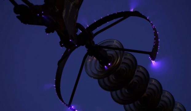
Corona effect in transmission line:
Corona is phenomenon which are related to electrical transmission it can be seen in transmission lines which can carry high voltage about 33 KV or above. The effect look like violet glows spread across the lines conductor.
Mechanism of corona effect:
When the alternating current flow across the two conductors of the transmission line whose spacing is large as compare to the diameter. Then air subjected to the dielectric effect, as the value of the voltage increases the air subjected to more dielectric strength. Some electrons escape from the conductor to air and ionize it.
Let us consider a conductor having 400KV voltage so due to high voltage in the conductor some voltage will be present around the conductor. The air near the conductor will act as dielectric. The air dielectric strength at normal temperature and normal pressure is 30 KV/Cm which means that if we the voltage is above 30 KV the air will be ionize and current will flow through it which is called air breakdown. This result electrical discharge around the conductor due to the flow of these electrons giving rise to the violet glow and also ozone gas is produce. If voltage across the line conductor is increase then the glow become more intense.
This light will not always show to us because of the several conditions which are:
-
Disruptive critical voltage
It is the minimum voltage required to ionize the air when the voltage is above the disruptive critical voltage the air will be ionize.
-
Visual critical voltage
It is the minimum voltage require to corona glow when the voltage is above the visual voltage then we will see the corona glow. This voltage can be different under different conditions. In rainy season it is less means we can see at low voltage and in non-rainy season it is maximum.
Let us consider that disruptive critical voltage is 30 KV then the visual critical voltage will be round about 50 KV to 60 KV. Than we will see the corona effect in transmission lines.
Effect of corona:
- Noise
- Electromagnetic interference
- Insulation damage
- Power loss
Factors affecting corona effect:
Atmospheric condition:
Corona effect will be seeing mostly during rainy season due to the presence of the water molecules in the air. Due to which the visual critical voltage will be decrease and corona effect will be maximum. In normal condition the corona effect is minimum.
Line voltage:
When the line voltage of the transmission line is maximum then the electrostatic field will be maximum due to which the ionization of the air will also be maximum and the corona loss will be maximum.
Nature of the conductor surface:
If the conductor is completely round than the corona loss in the conductor will be less but in the transmission line we use ASCR conductor because it is strong and flexible. If we use circular conductor it will break and also it is not flexible.
Effect of frequency:
When the frequency is maximum the corona loss will be also maximum because there is relation of the corona with the frequency when the frequency is maximum the corona effect will be maximum and vice versa.
Methods of reducing corona loss:
Conductor diameter or spacing between conductor:
When we increase the diameter and spacing between conductor the corona loss will be decrease.
Operating voltage:
If we decrease the operating voltage the corona loss will be decrease because there will be no air ionization due to which no corona loss will be produce.
Discover more from Electronic Clinic
Subscribe to get the latest posts sent to your email.