Triac construction, Working, and Uses
Last Updated on May 31, 2022 by Engr. Shahzada Fahad
Table of Contents
Triac Introduction:
Triac means a device that triggers AC. A semiconductor device or thyristor, which consists of three terminals and four layers and which if properly energized or activated, can conduct in any direction, is called a triac. Or it is a device that can block voltage of any polarity, however, can transmit current in any direction on receiving a pulse on its solitary gate. (Remember, diac has two terminals while triac has three terminals). Basically, triac works like two silicon control rectifiers fixed parallel in opposing directions or an SCR, the gate terminal of which is common. In other words, it is a device that can conduct in both directions irrespective of bias polarity when provided a pulse. Triac can also be defined in the following words.
Triac is such a bi-directional latching device, which functions like two parallel SCRs fixed in opposite directions (The characteristics of a four-layer switch under which it remains ON even after depletion of excitation, is called latch). Triac is very useful for AC loads power control due to its capability of conducting in both directions. However, its power or current handling capacity is comparatively less with respect to an SCR. Therefore, it is not applied in high-power rectified DC systems.
TRIAC Construction
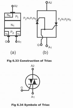
A triac has three terminals which are known as anode A1, anode A2, and gate G, as illustrated vide figure 6.33 (a). Triac consists of two inverse parallel connected SCRs the gate terminal of which is common. In other words, two SCRs connected parallel in inverse directions, so that their gate terminal is common, to become a triac (figure b). In figure 6.34, triac symbol has been illustrated, which clearly indicates that it is composed of two inversely connected SCRs having a common gate. Triac basically has four large layers of PNPN, however, there are additional N layers on lower P region as well which are manufactured by means of film technique. In figure 6.35, a specific triac pellet has been displayed.
Figure 6.33 construction of triac
Figure 6.34 symbols of triac
Positive Gate Voltage
Providing positive voltages on a gate or making the gate positive (with respect to A1) current carriers start flowing as a consequence of a positive P2-N2 junction. Thus, conduction commences.
Negative Gate Voltage
Negative gate voltage forward bias P2-N2 junction and penetrate current carriers, resultantly conduction kicks off. From the above discussion, it has become clear that every triac anode has two (i.e. four in all) triggering modes.
Voltage Current Characteristics (V/I Characteristics)
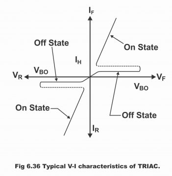
Peculiar characteristics of triac have been illustrated in figure 6.36. As is evident from the diagram, like an SCR, triac exhibits forward blocking and forward conducting characteristics. Its main terminal can supply voltages of any polarity. Further, it is capable of latching current in any direction. Triac’s rating can also be described in gate voltage apart from voltage and current. Remember that if triac is used at any frequency below 60 c/s, voltages on the sine wave diminish so much that triac cannot go ahead with its conduction and it turns off due to the non-presence of a pulse on gate.
Figure 6.36 typical V/I characteristics of triac
TRIAC Uses
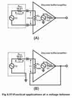
The basic application of a triac has been illustrated in figure 6.37. Here, it has been used for control of AC power fleeting towards the load. It controls power, turning it on or off similar to a switch during a positive and negative half cycle of input AC power. During the positive half cycle input, diode D1 is forward biased. Diode D2 is reverse biased and positive according to gate A1. The point of initiation of conduction can be changed via adjusting or varying the value of R (that’s the firing point of a triac is set through R)
Figure 6.37 control of AC power by Triac

Other uses of triac are as follows:
1). It is used as a static switch for turning an AC power on or off
2). It is used for reducing radio interference
3). It is used as lamp dimmer for control of light
4). It is also used for control of motor speeds
5). It is also used for full power and half power operation
In figure 6.38, triacs of different ratings and shapes have been illustrated

Triac Phase Control or Power Control
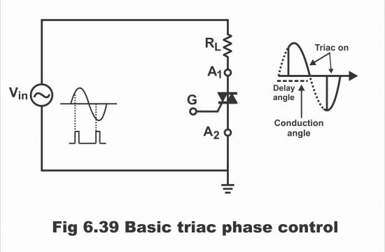
Just like an SCR, Triac can also be used for control of average load power via the phase control method. Under this situation, triac is triggered in such a manner that AC power is provided to load every controlled part of half-cycle (i.e. Triac can be triggered in any part of an AC power half-cycle at any specific part). During every positive AC half cycle, Triac remains off for a certain interval. This particular interval is called angle delay (which can be measured in degree). After this delay angle, Triac turns on immediately as a result of triggering (i.e. it resumes conducting). Thus, during the remaining part of the positive half-cycle (i.e. excluding delay angle, remaining part of the positive half cycle), Triac transmits current through the load. The remaining interval of positive half cycle, during which triac conducts, is known as the conduction angle. In figure 6.39, triac’s operation has been elaborated along with the delay angle and conduction angle. Remember that the same process takes place in the negative half cycle as well with the only exception that the direction of flow of current passing through the load is inverse as compared to its direction in a positive half cycle. This has been clarified in the figure.
Figure 6.39 basic triac phase control
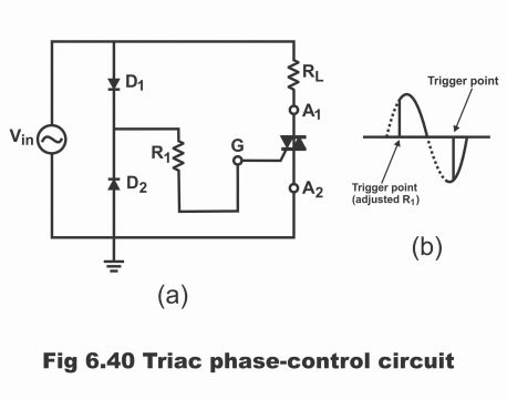
An example of phase control via usage of a triac has been explained in figure 6.40(a). Trigger pulses are provided on triac’s gate through a diode used in the circuit. During a positive half cycle, diode D1 conducts. The point of the positive half cycle, at which a triac triggers on, this point, is set via changing the values of R1. Remember that during this part of the AC cycle, A1 and G are positive with respect to A2.
Figure 6.40 triac phase control circuit
Diac-Triac Circuit for AC Power Control
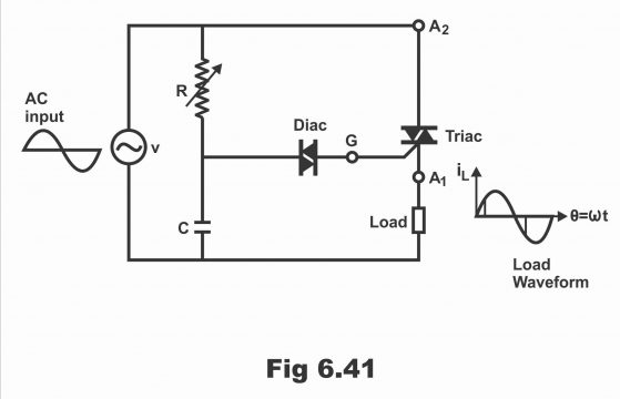
In figure 6.41, the circuit for controlling the power of an AC load has been displayed. It consists of a diac and triac. In this circuit, diac firing is controlled by means of adjusting the value of R. When A1 is positive with regard to A2, and when A1 is negative with respect to A2, triac trigger occurs. In the figure, diac has been fixed between the RC circuit and triac gate. When the value of a capacitor’s voltage is quite high (i.e. when the value exceeds the total of gates’ forward drop and diac’s breakover voltage), diac tends to fire. As soon as diac fires, charged capacitor provides a pulse on the gate by means of discharging. As a result, triac triggers and starts conduction. As a variable resistor R controls the time constant, on which the capacitor begins to charge thus, the firing angle (α) of a triac can be changed or controlled according to needs by means of R. If the value of R is raised inordinately, the charging process will be delayed or it will get slower. As a result, the firing angle will expand, When A2 gets negative with respect to A1, polarities of all voltages become reverse or inverse and triac starts conduction by triggering on a part of the negative half cycle. The firing angle in a practical circuit can be adjusted between zeros to 180ᵅ. Thus, the load current can be transmitted through the input’s nearly full cycle or a very small part input’s cycle. As the current wave form’s positive and negative areas are mutually equal, thus the value of the average current is zero.
Phase Control Circuit Using Triac and Diac
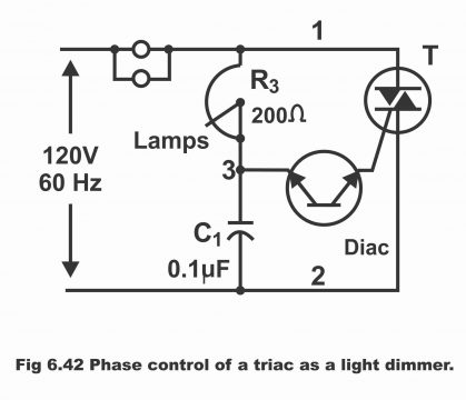
In figure 6.42, a phase control circuit comprising triac and diac has been illustrated, which acts as a light dimmer controller for an incandescent lamp (up to 700 watts). In this circuit, lamplight can be reduced or increased by changing the values of variable resistor R3 (e.g. if R3 is rotated clockwise, lamp light intensifies). . Capacitor C1 charges at the commencement of every half cycle through lamp load and R3 resistance (before triac T gets fired). As a result of the C1 charge, AC voltages at point 3 enhance. When point 3 voltages increase above a diac’s set breakover value (e.g. 30 volts), diac starts to conduct i.e. it turns on. As soon as diac conducts, capacitor C1 gets discharged via the triac’s gate. Thus, triac also starts to conduct after receiving a pulse on its gate, which provides
AC voltages parallel to lamp for this part of half cycle.
During next negative half cycle, points 1 and 3 are negative (due to a change in the polarity of input AC supply) and C1 will charge according to inverse polarity. Diac then triggers on this breakover voltage value (i.e. on the same 30 volts level), and triac fires on this phase delay exactly in the form of a positive half cycle. If R3 resistance is increased, C1 starts charging slowly and it thus requires a lot of time for reaching the 30-volt level or for storing a charge of 30 volts in its every half cycle. Thus, a very negligible share of AC voltage wave is received on lamps (i.e. as a result of sufficient time delay, trigger action occurs in some sections of half-cycles and resultantly very small voltages are passed on to lamps). Thus, lamps become dim or let out a dim light. Thus, lamplight can be changed through variations in values of R3 and changing triac’s triggering point according to need. If a thermistor is used in place of the reo-state R3, this circuit is used to control a furnace blower motor instead of lights. At low furnace temperatures, thermistor will transmit low current, thus triac will be unable to fire. When furnace temperature gets exceedingly high, thermistor lowers its resistance. Thus, C1 charges quickly. It fires in the beginning of the half-cycle at T and then disappears after supplying AC voltages to the blower motor.
Figure 6.42 phase control of a triac as a light dimmer
Triac as a Static Switch
A triac can also be used as a static switch just like a transistor for connecting electrical load with the power source or for detaching from the power source. We know that when two back-to-back fitted SCRs are used for control of AC circuits, every SCR turns off in the half-cycle. (Remember that triac’s construction is also similar to two back-to-back SCRs which also have an attached lead). However, when the current is zero, triac should turn off in a very short time. In fact, in the case of resistive load, triac’s off time starts with a reduction in the currents’ holding level. This continues till applied voltages in the next half-cycle reach the break-over value. In the majority of applications, this time is quite sufficient.
Under the situation of inductive load, triac’s commutation or triac’s off process affects due to the phase shift generated via inductance. Triac current becomes zero after a change in the polarity of applied current (because current leaks from the voltage in inductive load). When the current is zero and triac tries to turn off, rapidly approaching voltages appear parallel to terminals. The ratio of these voltages (dv/dt) is sometimes such that triac gets fired during the period. This leak current generated via inductive load intrudes into triac’s switching operation. (i.e. it does not allow triac to switch off quickly). Therefore, an RC circuit is used parallel to triac for improving its switching performance (figure 6.43). When triac conducts, the resistor confines the charge of the capacitor.
In figure 6.43, a simple triac switching circuit for control of AC load current has been illustrated. A micro switch, magnetic read switch or other compact switching devices can also be fixed on the circuit instead of this switch. When the switch is open, triac does not conduct and no current passes through a load. When switch is closed and line terminal A is positive, T2 and gate both are positive. In such a condition triac tends to trigger and turn on and the flow of current through the load commences. During the next half-cycle, when T2 and gate both become negative, triac conducts in the inverse direction. Thus, under this mechanism, this tiny device is used for switching high currents.
For further clarification, a switching circuit along with R2 and C2 has been demonstrated, in which gate current is passed on via closing a tiny contact “S”. As a consequence, triac T fires at the start of every half cycle provided AC voltages are being provided on load. When triac fires, there exists only a few volts parallel to it, due to which gate’s current pulse stops (in case of resistor load). When the controlled load is inductive and triac current stops, R2 and C2 are included for putting a limit on voltage increase ratio (dv/dt) parallel to triac. This assists in turning the triac off.
Figure 6.43 simple circuits for triac switching
Figure 6.44 full-wave AC is cross L when S closes firing the triac

A light Dimmer Using Triac
A simple circuit for controlling the light electricity through the application of a triac has been shown in figure 6.45. When A1 is positive with respect to A2, the gate receives a positive trigger or pulse with respect to A2, due to which triac turns on. If Rv is set at a lower value, triac will turn on immediately at the beginning of a positive half cycle. If Rv is set at a high value, triac will turn on belatedly for a positive half cycle. Thus, by changing the setting of Rv, the number of voltages received on load (i.e. electric bulb) can easily be controlled. When A1 is negative with respect to A2, the gate receives a positive trigger with respect to A1. And according to the Rv setting as mentioned above, triac turns on. Thus, the action of controlling a bulb’s light can very easily be carried out through the application of a triode as compared to a complex diode.
Figure 6.45 light dimmer using triac
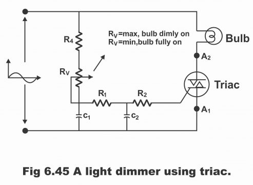
It has got to be remembered that the Ra resistor has been included in the gate circuit only because if the value of Rv is set to zero, a specific minimum resistance value should be present on the circuit for limiting the gate current. If this precautionary measure is not kept in mind, setting the Rv value at zero could render the SCR gate useless on account of a limitless gate current.
A Triac Time Delay Relay
In figure 6.46, the Triac time delay circuit has been displayed. In this circuit, triac T energizes relay CR on the final end of time delay (which is set via (R1+R2) and C1). When upper line 2 is more positive, electrons charge C1 via lower line 1, and then complete the circuit by reaching the upper line 2 vides R1, R2, and diode D. But as switch S is touching “Reset”, therefore triac does not fire. As triac’s gate terminal connects via a low-value resistance R4 near 4, which acts as a part of voltage dividers R1-R2-R3-R4. When switch S is connected with START, the potential existing on C1 terminal 3 expands further during every positive half-cycle via adjusting the value of R1. After desired delay or lapse of desired time, terminal 3 potential reaches closer to diac’s breakover voltage. As a result, diac turns on, and C1 sets on discharging. Thus, triac receives an electron pulse via diac and triac gate. When triac’s upper terminal 2 is positive, triac fires at the beginning of every half cycle. Thus, CR relay starts operating (i.e. turns on).
Figure 6.46 triac time-delay relay

No voltages are provided parallel to C2 or R5 before triac starts firing. When a fired tired triac provides positive voltages parallel to coil relay CR, these voltages also appear parallel to C2 and R5. When line voltages are reversed, that’s their polarity changes, C2 charges due to flow of electrons via R5, switch S, and triac’s gate. This current continues to flow even if the upper part of triac is negative. Thus, triac fires again at the start of every negative cycle. Coil CR continues to receive full-wave AC voltage until S moves towards RESET. Then C1, discharges through R3 and R4. Thus, the potential of point 3 reduces and triac does not fire during the next positive half-cycle as a result of diac current. Thus, no voltages exist parallel to CR coil nor any charging current exits on C2, which could enable a triac to fire in the negative half cycle. Consequently, the CR relay gets off just drops out.
Previous Topic: DIAC construction, Working, and Uses
Next Topic: Unijunction Transistor UJT
For electronics and programming-related projects visit my YouTube channel.
Discover more from Electronic Clinic
Subscribe to get the latest posts sent to your email.