ZMPT101B 80-250V AC Voltage Sensor with Arduino, Voltage Monitoring
Last Updated on September 21, 2024 by Engr. Shahzada Fahad
Table of Contents
ZMPT101B AC voltage Sensor:
ZMPT101B 80-250V AC Voltage Sensor with Arduino, Voltage Monitoring- In today’s article, you will learn how to measure Mains AC voltage using the ZMPT101B 250 volts AC voltage sensor, Arduino Nano or Arduino Uno, and an SSD1306 Oled display module.
Since this is my first article and video on the ZMPT101B AC voltage sensor module so I will try my level best to explain each and every detail including.
- The ZMPT101B mains voltage sensor technical specifications.
- Pins description.
- Circuit diagram.
- How to install all the required libraries.
- Arduino programming.
- The ZMPT101B AC voltage sensor calibration. And
- Practical demonstration.
So, without any further delay let’s get started!!!
Amazon Links:
Arduino Nano USB-C Type (Recommended)
*Disclosure: These are affiliate links. As an Amazon Associate I earn from qualifying purchases.
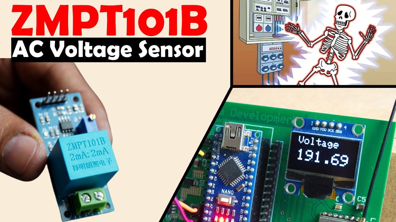
ZMPT101B 250V AC Mains Voltage Sensor:
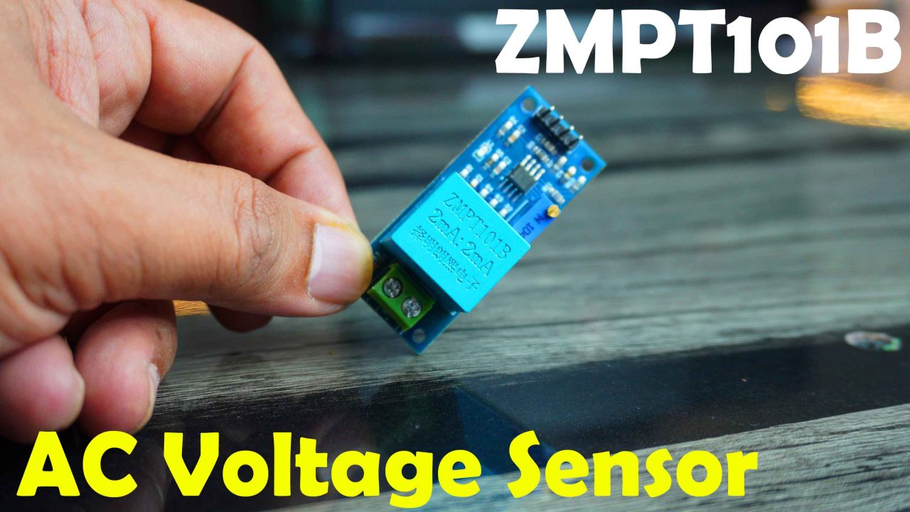
The ZMPT101B is a voltage sensor module commonly used for measuring alternating current (AC) mains voltage. It is designed to work with a voltage range of 80 to 250 volts AC. The module includes a voltage divider circuit and an internal operational amplifier to provide an analog output proportional to the measured voltage.
The ZMPT101B can be used in various applications, such as power monitoring, smart home automation, energy management systems, and industrial control systems. It is commonly utilized in projects where measuring the AC mains voltage is required for monitoring or control purposes.
It is important to note that when working with mains voltage, proper safety precautions should always be taken, and it is advisable to consult relevant electrical codes and standards. Additionally, if you plan to use the ZMPT101B module, it is recommended to refer to the manufacturer’s datasheet and documentation for detailed specifications, wiring diagrams, and usage guidelines specific to the module.
ZMPT101B Technical specifications:
- This is a compact single-phase AC Voltage Sensor module based on the micro-precision voltage transformer ZMPT101B.
- Turns Ratio: 1000:1000
- The Rated Input and Output current is 2mA.
- Voltage range is between 80 and 250V AC.
- The high precision on-board Op-Amp circuit is based on the LM358 Operational amplifier IC.
- Operating Temperature: -400 C to ±600
- The supply voltage is 5 volts to 30 volts DC.
- With the help of on-board potentiometer the output voltage can be adjusted. In simple words it is used for calibration. I will practically demonstrate this in a minute.
ZMPT101B Pinout description:
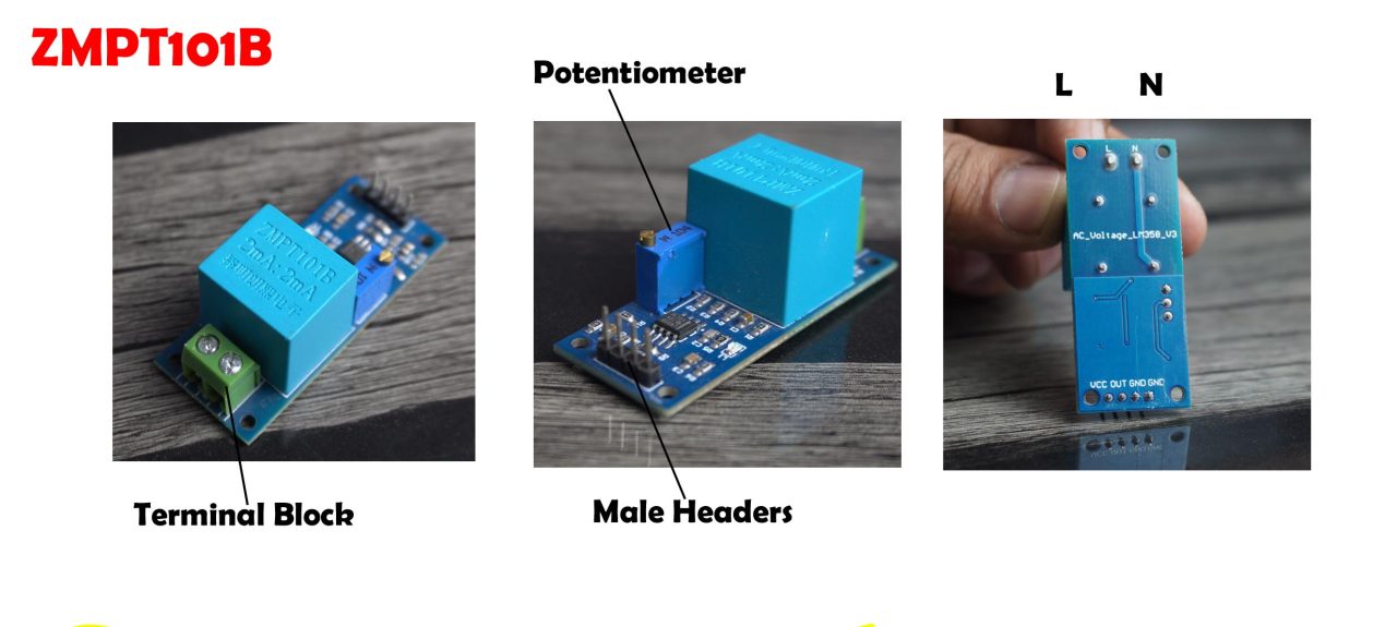
We have a terminal block on one side and 4 male headers on the receiver side. Connect the Mains AC voltage Live and Neutral wires to the L and N contacts on the ZMPT101B AC voltage sensor using the terminal block.
The 4 male headers are clearly labeled as VCC, OUT, GND, GND.
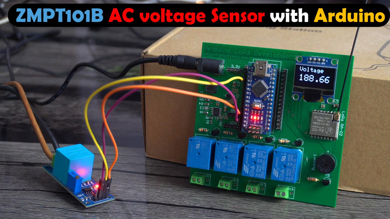
ZMPT101B voltage Sensor with Arduino:
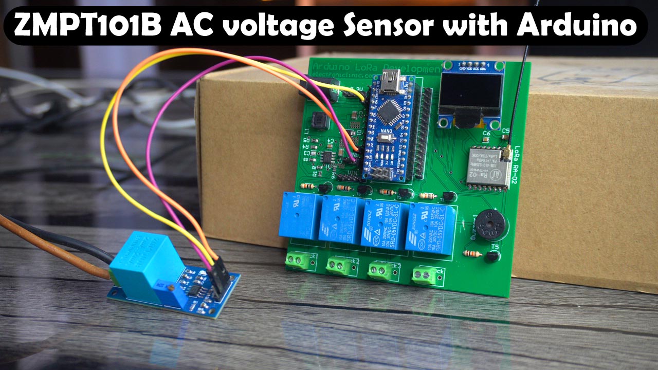
I am using my newly designed Arduino Nano and LoRa based development board. But you can also do the same exact connections on a breadboard. And instead of using Arduino Nano you can also use Arduino Uno.
Anyway, The VCC and GND pins of the ZMPT101B voltage sensor are connected to the Arduino 5V and GND pins. Whereas the voltage sensor OUT pin is connected to the Arduino Analog pin A0.
The SSD1306 Oled display module VCC and GND pins are connected to the Arduino 3.3V and GND pins. Whereas the SCL and SDA pins are connected to the Arduino analog pins A5 and A4. A5 is the SCL and A4 is the SDA.
The 5V buzzer is connected to the Arduino Digital pin D4. If your only goal is to measure the AC mains voltage then there is no need to use the buzzer. But if you want to monitor the Over-voltage and Under-voltage then you can use this buzzer. You will only need to define the over-voltage and under-voltage limits in the programming.
You can read my previous article, if you want to make the same development board. Or you can follow this circuit diagram if you want to manually wire up all the electronics.
ZMPT101B with Arduino, Circuit:
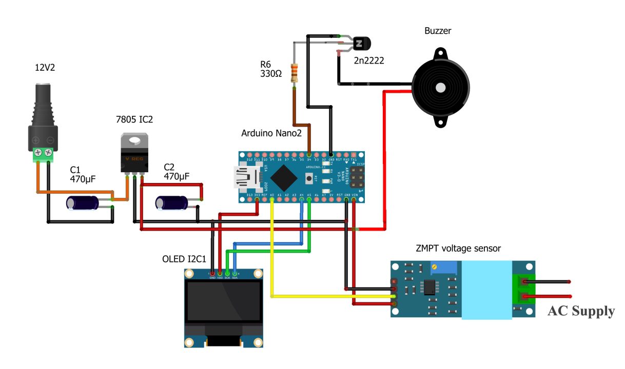
- Connect the VCC pin of the ZMPT voltage sensor with 5V of the Arduino Nano.
- Connect the Vout pin of the ZMPT voltage sensor with A0 pin of the Arduino Nano.
- Connect the Ground pin of the ZMPT voltage sensor with Ground of the Arduino Nano.
- Connect the VCC of the OLED with 3.3V of the Arduino Nano.
- Connect the ground of the OLED with Ground of the Arduino Nano.
- Connect the SDA pin of the OLED with A4 pin of the Arduino Nano.
- Connect the SCL pin of the OLED with A5 pin of the Arduino Nano.
- Connect the buzzer with D4 pin of the Arduino Nano.
Now, let’s go ahead and take a look at the programming.
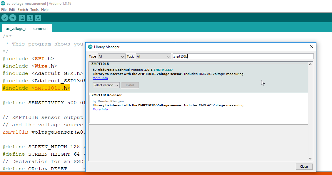
Download the Required Libraries:
You will also need to download the ZMPT101B library. Go to the Sketch menu > then to Include Library > and click on the Manage Libraries. Search for the ZMPT101B library and install it.
ZMPT101B Arduino Programming:
|
1 2 3 4 5 6 7 8 9 10 11 12 13 14 15 16 17 18 19 20 21 22 23 24 25 26 27 28 29 30 31 32 33 34 35 36 37 38 39 40 41 42 43 44 45 46 47 48 49 |
/** * This program shows you how to use the basics of this library. */ #include <SPI.h> // include libraries #include <Wire.h> #include <Adafruit_GFX.h> #include <Adafruit_SSD1306.h> #include <ZMPT101B.h> #define SENSITIVITY 500.0f // ZMPT101B sensor output connected to analog pin A0 // and the voltage source frequency is 50 Hz. ZMPT101B voltageSensor(A0, 50.0); #define SCREEN_WIDTH 128 // ORelay display width, in pixels #define SCREEN_HEIGHT 64 // ORelay display height, in pixels // Declaration for an SSD1306 display connected to I2C (SDA, SCL pins) #define ORelay_RESET -1 // Reset pin # (or -1 if sharing Arduino reset pin) Adafruit_SSD1306 display(SCREEN_WIDTH, SCREEN_HEIGHT, &Wire, ORelay_RESET); int buzzer=4; void setup() { Serial.begin(115200); pinMode(buzzer,OUTPUT); // Change the sensitivity value based on value you got from the calibrate // example. voltageSensor.setSensitivity(SENSITIVITY); display.begin(SSD1306_SWITCHCAPVCC, 0x3C); delay(2000); display.clearDisplay(); display.setTextColor(WHITE); } void loop() { // read the voltage and then print via Serial float voltage = voltageSensor.getRmsVoltage(); Serial.println(voltage); display.clearDisplay(); display.setCursor(10,0); display.setTextSize(2); display.setTextColor(WHITE); display.print("Voltage"); display.setCursor(10,25); display.setTextSize(3); display.setTextColor(WHITE); display.print(String(voltage)); display.display(); delay(1000); } |
Code Explanation:
|
1 |
#define SENSITIVITY 500.0f |
We simply define the sensitivity.
|
1 |
ZMPT101B voltageSensor(A0, 50.0); |
Then we define the pin and the frequency. In my case, I am using Analog pin A0 and the mains frequency on my side is 50Hz. If on your side the frequency is 60Hz then use 60Hz.
|
1 2 3 4 5 6 7 8 9 |
#define SCREEN_WIDTH 128 // ORelay display width, in pixels #define SCREEN_HEIGHT 64 // ORelay display height, in pixels // Declaration for an SSD1306 display connected to I2C (SDA, SCL pins) #define ORelay_RESET -1 // Reset pin # (or -1 if sharing Arduino reset pin) Adafruit_SSD1306 display(SCREEN_WIDTH, SCREEN_HEIGHT, &Wire, ORelay_RESET); |
All these other instructions are for the SSD1306 Oled display module.
Inside the void setup() function, I have activated the serial communication. I set the buzzer as output. Next, I set the voltage sensor sensitivity and I activated the Oled display module.
|
1 |
float voltage = voltageSensor.getRmsVoltage(); |
Inside the loop() function only this instruction does all the things. We simply read the voltage and then print it on the Oled display module.
Next, connect your Arduino board to the laptop and upload the program.
ZMPT101B Practical Demonstration:
I am going to use a 12V adaptor to power up my Arduino Development board. Next, I am going to supply AC voltage to the ZMPT101B.

You can see the measured AC voltage on the Oled display module. I don’t know if this value is correct so I am going to use my digital multimeter to measure the actual mains AC voltage.
As you can see the actual voltage is 189 volts AC while the measure voltage fluctuate around 190 volts. This value is pretty close and for me it’s acceptable. If on your side the voltage difference is more than you can use this potentiometer to fine tune the value. While calibrating the sensor make sure you don’t touch ac voltage wires or the contacts on the bottom side of the PCB. As it can be really dangerous.
I fine tuned my ZMPT101B voltage sensor and now the measured value is pretty close to the actual voltage. Its ok if you see small fluctuations.
Now, we can define limits in the programming. Let’s say when the voltage drops below 100 volts, the Arduino can automatically turn off the AC, TV, or any other sensitivity loads. And the same thing you can do for the over-voltage. On my designed Arduino development board, I have also used LoRa Ra-02 transceiver module which can wirelessly send data over a long distance around 5 kilometers. So, using the LoRa module I can monitor a power station or I can use it to check if the AC Voltage is available or not. In my upcoming video, I will use it for making a power monitoring system. So, that’s all for you now.
Watch Video Tutorial:
Discover more from Electronic Clinic
Subscribe to get the latest posts sent to your email.


i love this project . i am working on using ZMPT101B in project with MCU ESP32 . i need to know if this Arduino code can work with the ac voltage sensing in ESP chip ?
How did you make the diagram and circuit for the relays?