Arduino DC Motor Speed Control with Encoder – Complete Tutorial
Last Updated on May 9, 2026 by Engr. Shahzada Fahad
Table of Contents
How to control dc motor with encoder:
Arduino DC Motor Speed Control with Encoder- I have been using different types of stepper motors, Servo motors, and DC Motors for quite a long time in different intermediate and advanced level projects. DC motors are more frequently used than Stepper Motors and Servo Motors. If you have watched my videos and read my articles then you should know DC motors are quite different from Stepper Motors and servo Motors.
These three types of motors have a different construction. The stepper motors and servo motors are designed in a way that we can control their position. We can control the steps in the forward and reverse directions.
Servos can move from 0 to 180 degrees, so you can move to any position between 0 and 180. Likewise, in stepper motors, you can control the steps precisely and this is the reason stepper motors are used in CNC machines, 3d printers, etc. On the other hand, when a dc motor is powered up it immediately starts rotating, it continuously rotates, you can’t exactly control its position until you use a specific technique.
You can’t 100% control a DC motor like Stepper motor and Servo, but if you add an encoder it can really change the whole game. With an encoder being added, you can keep track of the motor revolutions, the amount of distance it has covered, and this way you can make a nice feedback system that can be used to control the DC motor. Then you can stop the DC motor at the position where you want it to stop. The control of a DC motor using an encoder is not that simple, you just simply can’t start by adding an encoder with the DC Motor and start controlling the DC motor, to use an encoder you will need a controller, the controller will read the encoder and then will accordingly control the DC motor as per the pre-defined instructions written by the programmer.
for this project, you will need a microcontroller board like the Arduino Uno or Arduino Nano, or Arduino Mega, or Arduino pro mini, etc. I know beginners are more comfortable with Arduino Uno, Arduino mega, and Arduino Nano, so I will start with the Arduino Uno, the same connections and programs you can also try on Arduino Nano and Arduino Mega. To get started, you will need Arduino Uno, a Motor driver, a DC Motor, and of course an Encoder. To read the Encoder, we will connect the encoder output pins with Arduino’s pins 2 and 3 which are the interrupt pins. The power wires of the encoder will be connected with the Arduino’s 5V and GND. To keep things simpler, I will start with the simple example code in which I will use pins 2 and 3 as the normal digital pins, we won’t activate the interrupts and then in the second example code, we will use the interrupts. Without any further delay, let’s get started!!!
Real-World Applications
The precision control offered by encoder-equipped motors is essential in modern automation. Robotic arms rely on them to calculate precise joint angles, while CNC machines and 3D printers use them to ensure tools move accurately across X, Y, and Z axes. Additionally, they are vital in conveyor belt systems for tracking product position and speed to ensure synchronized assembly line operations.
What is a Quadrature Encoder?
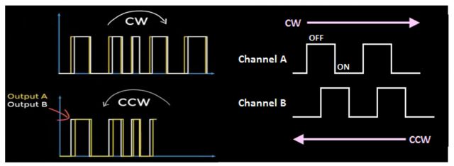
A quadrature encoder is a type of incremental rotary encoder that converts angular motion into digital pulses. It features two output channels, Channel A and Channel B, which are physically offset by 90 degrees. This phase shift allows the Arduino to determine not only the speed (via pulse frequency) but also the direction of rotation by observing which channel leads the other.
Pulses Per Revolution (PPR) defines the resolution; a higher PPR provides finer control. Incremental encoders track relative position changes from a starting point, making them ideal for speed and position tracking. In contrast, Absolute encoders provide a unique digital code for every position, allowing the device to know its exact orientation immediately upon power-up without needing to “home” or calibrate.
Amazon Links:
Arduino Nano USB-C Type (Recommended)
*Disclosure: These are affiliate links. As an Amazon Associate I earn from qualifying purchases.
DC Motor with Encoder + Arduino, Circuit Diagram:
The type of the DC motor as you can see in the circuit diagram given below has a built-in encoder. So, it’s totally up to you whether you want to use it as the simple dc motor or you want to use the encoder, or you can use the motor and encoder together at the same time. As you can see in the circuit diagram, the power wires which are the Red and Black wires are not connected but the encoder wires are connected. For this first example, we will only be using the encoder to understand the basics this way you will easily understand how an encoder works. So, we will rotate the motor shaft by hand to see the trigger signals.
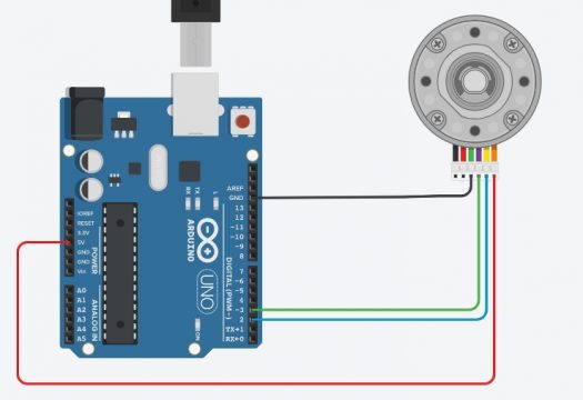
An encoder works by observing changes to the magnetic field created by a magnet attached to the motor shaft, as the motor rotates the encoder outputs will trigger periodically. When the magnet spins clockwise, output “a” will trigger first, and when rotated counterclockwise on the other hand output “b” will trigger. This way you know exactly which way the motor shaft is rotating. This can be quite handy in situations where you need to control the forward and reverse movement of the DC Motor.
Let’s write a very simple program to understand how an encoder works and how to read the encoder outputs.
Arduino Encoder Code:
|
1 2 3 4 5 6 7 8 9 10 11 12 13 14 15 16 17 18 19 20 21 |
#define ENCA 2 // pin2 of the Arduino #define ENCB 3 // Pin3 of the Arduino int ENCA_DATA; int ENCB_DATA; void setup() { Serial.begin(9600); // Activates Serial communication pinMode(ENCA,INPUT); // sets pin2 as the input pinMode(ENCB,INPUT); // sets pin3 as the input } void loop() { ENCA_DATA = digitalRead(ENCA); // We simply read Pin2 of the Arduino and store the result in variable ENCA_DATA ENCB_DATA = digitalRead(ENCB); // We simply read Pin3 of the Arduino and store the result in variable b Serial.print(ENCA_DATA*5); Serial.print(" "); Serial.print(ENCB_DATA*5); Serial.println(); } |
Arduino Encoder Code Explanation:
We don’t need any libraries for this basic program. First of all, I started off by defining the Arduino pins 2 and 3. I will call these pins the ENCA and ENCB. These two pins will be connected with the Encoder outputs.
#define ENCA 2
#define ENCB 3
Next, I defined two variables ENCA_DATA and ENCB_DATA.
int ENCA_DATA;
int ENCB_DATA;
Next, we will need to tell the Arduino whether we want to use the Serial communication? And the pins we just defined are going to be used as the inputs or outputs? All this is done in the void setup() function.
void setup() {
Serial.begin(9600);
pinMode(ENCA,INPUT);
pinMode(ENCB,INPUT);
}
In the void setup() function, I simply activated the serial communication and I selected 9600 as the Baud rate. Next, I set the two pins ENCA and ENCB as the inputs using the pinMode() functions.
The void setup() function executes only once with the Arduino board is first turned ON. The actual code is placed inside the loop() function which executes repeatedly.
void loop() {
ENCA_DATA = digitalRead(ENCA);
ENCB_DATA = digitalRead(ENCB);
I simply defined a variable “ENCA_DATA” which is of the type integer. Then we read the ENCA pin using the digitalRead() function and store the value in variable ENCA_DATA, exactly the same thing I did for the ENCB.
Serial.print(ENCA_DATA*5);
Serial.print(” “);
Serial.print(ENCB_DATA*5);
Serial.println();
}
Next, to write outputs to the computer screen I used the Serial.print() and Serial.println() functions. Inside the parenthesis, you can see I am multiplying the values by 5 to make the plot easier to read.
All you need is to compile the code first to check if any keywords are misspelled, and then you can upload the code.
After the code has been uploaded, you can go ahead and open the Serial Monitor and select the 9600 Baud Rate. Now, you can start by rotating the DC Motor shaft which has the encoder. The Encode signal changes as you rotate the motor shaft, these changes are easier to understand with the serial plotter. So, output “a” is triggered when you rotate the shaft Clockwise and similarly, the output “b” is triggered when you rotate the shaft anti-clockwise. This code has nothing to do with the motor shaft position, the purpose of this code was just to help you understand how these two outputs “a” and “b” are triggered.
Now let’s measure the position of the DC motor shaft. Nothing is changed on the hardware side. We are using the same connections.
Position of the encoder Arduino Code:
|
1 2 3 4 5 6 7 8 9 10 11 12 13 14 15 16 17 18 19 20 21 22 23 24 25 26 27 28 29 30 31 |
/* * The purpose of this code is to count the ouput pulses or * the encoder outputs as you rotate the Motor shaft. You can run the * same code on the Arduino Uno, Arduino Nano, Arduino Mega, etc. */ #define Encoder_output_A 2 // pin2 of the Arduino #define Encoder_output_B 3 // pin 3 of the Arduino // these two pins has the hardware interrupts as well. int Count_pulses = 0; void setup() { Serial.begin(9600); // activates the serial communication pinMode(Encoder_output_A,INPUT); // sets the Encoder_output_A pin as the input pinMode(Encoder_output_B,INPUT); // sets the Encoder_output_B pin as the input attachInterrupt(digitalPinToInterrupt(Encoder_output_A),DC_Motor_Encoder,RISING); } void loop() { Serial.println("Result: "); Serial.println(Count_pulses); } void DC_Motor_Encoder(){ int b = digitalRead(Encoder_output_B); if(b > 0){ Count_pulses++; } else{ Count_pulses--; } } |
Position of the encoder Arduino Code Explanation:
This code is the modified version of the code that I just explained above. I made some changes, which I am sure you can clearly see. Let’s talk about these changes in detail. The pins 2 and 3 connections remain exactly the same.
#define Encoder_output_A 2 // pin2 of the Arduino
#define Encoder_output_B 3 // pin 3 of the Arduino
// these two pins has the hardware interrupts as well.
I defined a global variable Count_pulses and initially stored a value of 0 in it. As this is a global variable so I can access this variable from anywhere inside my Arduino code.
int Count_pulses = 0;
Inside the void setup() function, you can clear see the first three lines of code are exactly the same.
void setup() {
Serial.begin(9600); // activates the serial communication
pinMode(Encoder_output_A,INPUT); // sets the Encoder_output_A pin as the input
pinMode(Encoder_output_B,INPUT); // sets the Encoder_output_B pin as the input
attachInterrupt(digitalPinToInterrupt(Encoder_output_A),DC_Motor_Encoder,RISING);
}
This time I added this attachInterrupt(digitalPinToInterrupt(Encoder_output_A),DC_Motor_Encoder,RISING); this line of code. The attachinterrupt() function is used to activate the hardware interrupt. The attachinterrupt() function takes three arguments as the input. The first one is the pin digitalPinToInterrupt(Encoder_output_A), the second argument is the function name, this function will execute each time when an interrupt happens on the Encoder_output_A pin of the Arduino which is pin 2. The 3rd argument is to tell whether to take action on the rising edge or the falling edge. So, our interrupt setting is completed.
This time inside the loop function many things are changed. This time inside the loop() function we are only using 2 lines of code, the first line of code prints the text Result and the “Serial.println(Count_pulses);” which prints the value stored in the variable Count_pulses.
void loop() {
Serial.println(“Result: “);
Serial.println(Count_pulses);
}
DC_Motor_Encoder() function is a user-defined function it has no return type and does not take any arguments as the input. This is the function that is executed when an interrupt happens on pin2 of the Arduino. So, inside this function we are simply reading the Encoder_output_B pin, the value is stored in variable b. Next, we use an if condition to check if a signal is detected then increment the Count_pulses by 1 or else decrement the Count_pulses.
void DC_Motor_Encoder(){
int b = digitalRead(Encoder_output_B);
if(b > 0){
Count_pulses++;
}
else{
Count_pulses–;
}
}
Upload the code, open the serial monitor, and start rotating the encoder. Rotate the motor shaft in the clockwise direction and also in the anti-clockwise direction. In one direction the value will increase and in the other direction the value will decrease.
Driving the Motor with Encoder and Arduino:
Now, I am sure you have completely understood how an Encoder works, how the Encoder outputs are triggered, and then how to write a simple code to count the pulses. So far we were manually rotating the DC motor shaft to trigger the Encoder outputs, now to do everything automatically it’s time to connect a motor driver so that we can read the position measurements from the Encoder. Start by connecting the DC motor wires to the outputs of the motor driver circuit. The motor driver also needs an appropriate power supply, which you will need to select as per your DC motor specs. Next, connect the Motor driver ground to the Arduino ground, the PWM input of the motor driver should be connected to an Arduino PWM pin here I have used pin 5.
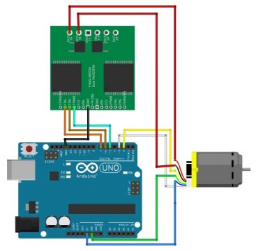
The other two motor driver pins can be connected to any of the remaining Arduino digital pins. Before writing the control algorithm, Let’s test the motor driver start by defining the pins that you connected to the motor driver.
Driving the Motor with Encoder, Arduino Code:
|
1 2 3 4 5 6 7 8 9 10 11 12 13 14 15 16 17 18 19 20 21 22 23 24 25 26 27 28 29 30 31 32 33 34 35 36 37 38 39 40 41 42 43 44 45 46 47 48 49 50 51 52 |
#define ENCA 2 #define ENCB 3 #define PWM 5 #define IN2 6 #define IN1 7 int pos = 0; void setup() { Serial.begin(9600); pinMode(ENCA,INPUT); pinMode(ENCB,INPUT); attachInterrupt(digitalPinToInterrupt(ENCA),readEncoder,RISING); } void loop() { setMotor(1, 25, PWM, IN1, IN2); delay(200); Serial.println(pos); setMotor(-1, 25, PWM, IN1, IN2); delay(200); Serial.println(pos); setMotor(0, 25, PWM, IN1, IN2); delay(20); Serial.println(pos); } void setMotor(int dir, int pwmVal, int pwm, int in1, int in2){ analogWrite(pwm,pwmVal); if(dir == 1){ digitalWrite(in1,HIGH); digitalWrite(in2,LOW); } else if(dir == -1){ digitalWrite(in1,LOW); digitalWrite(in2,HIGH); } else{ digitalWrite(in1,LOW); digitalWrite(in2,LOW); } } void readEncoder(){ int b = digitalRead(ENCB); if(b > 0){ pos++; } else{ pos--; } } |
It is useful to define a function that will set the motor direction and speed. The interface for the setMotor function, I have written here sets the direction and speed of a motor with the pins defined in the last three inputs. Inside the function, I have set the speed with an analog write command. if the direction integer is 1 then the motor will rotate one way by writing a high low combination to the input pins of the driver. If you reverse the order to a low-high combination the motor will rotate in the other direction. Inside the loop function, you can call the setMotor function to drive the motor also write the position to the serial line.
Control DC motor using Encoder feedback loop:
So far we have connected the controller motor driver and motor in a loop but we have not used the position signal from the encoder to control the motor position. We will use a feedback loop. In a feedback loop the control components are often referred to as the plant(motor) here that is the motor and the motor driver. The sensor(encoder) that we are using to measure position is the encoder. In order to actually control the position of the motor you need to provide it with a target position, then you take the difference between the target position and the measured position, the result is the error usually written as e(t).
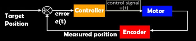
Now that the error has been computed you can use a controller to compute a control signal that is sent to the plant(motor). The control signal is configured so that it will attempt to reduce the error. The control signal is typically written as u(t).
In this project, we will use the PID control algorithm to generate the control signal u(t) the PID control signal is constructed using a sum of three terms a proportional, derivative, and integral term that is what PID stands for. The proportional term is the most important as it is directly responsible for reducing the error, the derivative and integral terms are typically used to smooth out the control system response. The three constants kp, ki and kd determine how strongly each term is represented in the control loop; you can adjust these constants to tune your response. You can estimate the integral and derivative of the error using the simple finite difference approximation. The integral term accumulates the error over time and the derivative computes how quickly the error is changing with the feedback control loop. Complete, you’re ready to write code to control the position of the motor.
DC Motor control with Encoder Feedback, Arduino Code:
|
1 2 3 4 5 6 7 8 9 10 11 12 13 14 15 16 17 18 19 20 21 22 23 24 25 26 27 28 29 30 31 32 33 34 35 36 37 38 39 40 41 42 43 44 45 46 47 48 49 50 51 52 53 54 55 56 57 58 59 60 61 62 63 64 65 66 67 68 69 70 71 72 73 74 75 76 77 78 79 80 81 82 83 84 85 86 87 88 89 90 91 92 93 94 95 96 |
#define ENCA 2 #define ENCB 3 #define PWM 5 #define IN2 6 #define IN1 7 int pos = 0; long prevT = 0; float eprev = 0; float eintegral = 0; void setup() { Serial.begin(9600); pinMode(ENCA,INPUT); pinMode(ENCB,INPUT); attachInterrupt(digitalPinToInterrupt(ENCA),readEncoder,RISING); Serial.println("target pos"); } void loop() { // set target position int target = 1200; //target = 250*sin(prevT/1e6); // PID constants float kp = 1; float kd = 0.025; float ki = 0.0; // time difference long currT = micros(); float deltaT = ((float) (currT - prevT))/( 1.0e6 ); prevT = currT; // error int e = pos-target; // derivative float dedt = (e-eprev)/(deltaT); // integral eintegral = eintegral + e*deltaT; // control signal float u = kp*e + kd*dedt + ki*eintegral; // motor power float pwr = fabs(u); if( pwr > 255 ){ pwr = 255; } // motor direction int dir = 1; if(u<0){ dir = -1; } // signal the motor setMotor(dir,pwr,PWM,IN1,IN2); // store previous error eprev = e; Serial.print(target); Serial.print(" "); Serial.print(pos); Serial.println(); } void setMotor(int dir, int pwmVal, int pwm, int in1, int in2){ analogWrite(pwm,pwmVal); if(dir == 1){ digitalWrite(in1,HIGH); digitalWrite(in2,LOW); } else if(dir == -1){ digitalWrite(in1,LOW); digitalWrite(in2,HIGH); } else{ digitalWrite(in1,LOW); digitalWrite(in2,LOW); } } void readEncoder(){ int b = digitalRead(ENCB); if(b > 0){ pos++; } else{ pos--; } } |
Start by defining global storage variables that can be used to save values between time steps, these are used in the finite difference estimates for the integral and derivative. The first thing that you need to do in the loop function is set a target for the control loop; the control signal will be adjusted over time as the measured position becomes closer to the target. Next, define the constants used in the PID control algorithm start by setting kp to 1 and kd and ki to 0. you can come back and adjust these later to compute the finite difference approximations. We need to compute the time difference t start by recording the current time in microseconds using the micros function then compute t in seconds by taking the difference between the current time and the previous time, be careful that you are performing floating-point arithmetic not integer arithmetic; complete the calculation by storing the current time in the previous time variable for use. In the next iteration of the loop, the error is computed as the difference between the target and measured positions here I have reversed the order because of the way that I wired the motor leads if you find that your control algorithm is not working you can try switching the sign of the error term as I did now compute the derivative and integral of the arrow signal using the finite difference approximations with all that work done you are finally ready to compute your control signal. it is surprisingly simple is not it this signal will tell the plant the direction and speed to turn the motor to send the signal to the motor. We need to convert it into a speed and direction start by computing the PWM signal as the floating-point absolute value of the control signal U.
You also need to cap the PWM signal at 255 as that is the maximum value we can write next to determine the direction by computing the sign of the control signal u with the motor speed and direction computed from the control signal call the setMotor function to write to the motor driver to complete the loop function store the previous value of the error also print your target and measure positions to the serial com, so you can test how well your control algorithm is performing with these parameters. I am seeing a little overshoot after reaching the target. In other words, the motor spins too far and has to reverse directions to achieve the target position one way to reduce overshoot is to increase the derivative term here I have set kd equal to 0.025 this is enough to completely remove the overshoot for this system. Once your system works to achieve a constant target try setting a target that changes with time here I have set a sinusoidal target depending on your target and loading conditions you will need to further tune your PID parameters.
Troubleshooting
Encoder Readings Jitter: This is often caused by electrical noise. Ensure you have a common ground between the motor power supply and the Arduino. You can also add 0.1µF capacitors between the encoder pins and ground to debounce the signal.
Motor Not Stopping at Correct Position: This typically results from “overshoot” caused by high momentum. Implement a PID (Proportional-Integral-Derivative) controller to slow the motor down as it approaches the target position.
Interrupt Conflicts: The Arduino Uno has interrupts on pins 2 and 3. If you move to an Arduino Mega, remember that interrupt pins differ (Mega supports interrupts on pins 2, 3, 18, 19, 20, and 21). Ensure your code references the correct interrupt pins for your specific board.
Troubleshooting — Common Problems and How to Fix Them
Problem 1: Encoder values are jumping randomly or counting in the wrong direction
Cause: The encoder wires are picking up electrical noise from the motor, or Channel A and B are swapped.
Fix:
– Keep your encoder wires physically separate from your motor power wires. Never run them alongside each other in the same bundle.
– Add a small 100nF ceramic capacitor between each encoder signal wire and GND on your breadboard. This filters electrical noise.
– If the motor counts in the wrong direction, swap the Channel A and B pin definitions in your code. You do not need to rewire anything physically.
Problem 2: Motor is running but encoder counts stay at zero
Cause: The encoder is not receiving power, or the signal wires are connected to the wrong Arduino pins.
Fix:
– Check that the encoder VCC wire is connected to 5V on your Arduino. Most hobby encoders work on 3.3V to 5V — check your encoder datasheet.
– On Arduino Uno, only pins 2 and 3 support hardware interrupts. Make sure your encoder Channel A goes to pin 2 and Channel B goes to pin 3.
– On Arduino Mega, you have more options: pins 2, 3, 18, 19, 20, and 21 all support interrupts.
– Open the Serial Monitor and print the encoder count every loop. If it never changes, the encoder signal is not reaching the Arduino.
Problem 3: Motor overshoots the target position and keeps oscillating
Cause: The kD (derivative) term in the PID controller is too low, or the motor has too much speed when it approaches the target.
Fix:
– Increase the kD value slowly — double it and test. Repeat until the oscillation stops.
– Reduce the maximum PWM value in your code so the motor approaches the target more slowly.
– Add a slow-down zone in your code: when the motor is within 50 counts of the target, limit the PWM to 40% maximum.
Problem 4: Motor vibrates or stutters instead of running smoothly
Cause: The kP (proportional) term is too high, causing the PID controller to overcorrect on every loop.
Fix:
– Cut your kP value in half and test. Keep reducing until the stuttering stops.
– Make sure your power supply can deliver enough current. A weak power supply causes voltage to drop under load, which makes the motor behave erratically.
– Check if your motor driver is overheating. Touch it carefully — if it is very hot, attach a small heatsink or reduce the motor speed.
Problem 5: Arduino resets randomly while the motor is running
Cause: The motor is creating voltage spikes that travel back through the power supply and reset the Arduino.
Fix:
– Add a large capacitor (470 microfarad or 1000 microfarad, rated at 25V or higher) across the positive and negative terminals of your motor driver power supply.
– Double-check that the motor power supply is separate from the Arduino power supply. They should only share the ground connection.
– If the problem continues, add a small diode (like 1N4007) in series with the motor driver power wire to block reverse spikes.
Problem 6: L298N motor driver gets very hot after a few minutes
Cause: The L298N is an older design with high internal resistance. It wastes a lot of power as heat, especially at currents above 1 amp.
Fix:
– Attach a metal heatsink to the top of the L298N chip. This is practically required for any project running more than 10 minutes.
– For motors that draw more than 1.5A, consider switching to a better driver such as the BTS7960 or the TB6612FNG, which are much more efficient.
– Make sure the PWM frequency in your code is not above 25kHz. The L298N does not handle very high frequencies well.
Frequently Asked Questions
Can I use this same code and circuit with ESP32 instead of Arduino Uno?
Yes, the ESP32 works very well for this project. In fact the ESP32 is better for this because almost every GPIO pin on the ESP32 supports interrupts, giving you much more flexibility in wiring. The main change you need to make is to declare your encoder position variable as volatile and use digitalPinToInterrupt() when attaching the interrupt. One important note: the ESP32 runs on 3.3V logic, so confirm that your encoder outputs are also 3.3V compatible. Most modern encoders work fine at 3.3V but always check the datasheet first.
What is the difference between an incremental and an absolute encoder?
An incremental encoder (like the ones used in this tutorial) counts pulses starting from zero each time the power is turned on. It does not remember its position after a restart — it only knows how far the motor has moved since the program started. An absolute encoder always knows its exact position even after the power is completely removed and restored. Absolute encoders cost significantly more but are essential for applications like robotic arms where you cannot re-home the arm every time you turn on the machine.
How do I calculate the actual RPM from encoder pulse counts?
Use this formula: RPM = (counts per second x 60) divided by (PPR x 4).
The multiplier of 4 comes from counting both the rising and falling edges of both encoder channels, which is called full quadrature decoding and gives you four times the resolution of the basic PPR.
Example: if your code counts 1320 pulses per second, and your motor encoder is 11 PPR with a 30:1 gearbox, the output shaft RPM = (1320 x 60) divided by (11 x 4) = 1800 RPM at the motor shaft, or 60 RPM at the gearbox output shaft.
My motor only has 2 wires. Can I still add an encoder?
If your motor has only 2 wires, it does not have a built-in encoder. You have two options. The first option is to buy a new motor that already includes an encoder. Search for “GA25 motor with encoder” or “N20 motor with encoder” on AliExpress or Amazon — these are affordable and come ready to use. The second option is to attach an external optical encoder wheel to the motor shaft, but this requires drilling and mechanical work that most beginners find difficult. For most people, buying a motor with a built-in encoder is the easier and cheaper option in the long run.
Can I control two motors with encoders at the same time on Arduino Uno?
This is tricky on Arduino Uno because it only has 2 hardware interrupt pins (pins 2 and 3), and a single quadrature encoder needs 2 interrupt pins for full direction detection. This means one Uno cannot do full quadrature decoding for two motors at the same time. Your options are: use Arduino Mega which has 6 interrupt pins and can handle two encoders fully; use only one channel per encoder (you lose direction information but still get speed counts); or use a dedicated encoder counter chip like the LS7366R which handles counting in hardware and communicates with Arduino over SPI, freeing up your interrupt pins.
What is PID and do I really need it for this project?
PID stands for Proportional, Integral, and Derivative. It is a control algorithm that helps the motor reach a target position or speed smoothly and accurately without overshooting. For simple projects like a wheeled robot that just needs to drive forward, you can skip PID and use simple on/off logic. But for anything that needs precision — robotic arms, camera sliders, CNC machines — PID makes a massive difference in performance. The good news is that the code provided in this tutorial already implements PID for you. All you need to do is tune the three values kP, kI, and kD for your specific motor through trial and error as explained in the article above.
Is this project safe for a total beginner?
Yes, this project is completely safe as long as you follow two basic rules. First, always use a motor driver (like the L298N) between your Arduino and the motor — never connect a motor directly to Arduino pins. Second, power the motor from a separate external power supply, not from the Arduino. The motor voltages used in this project (6V to 12V DC) are not dangerous to touch, and the Arduino operates at only 5V. Just be careful with your wiring, double-check connections before powering on, and you will be completely fine.
What Should I Build Next?
Now that you have successfully controlled a DC motor with an encoder, here are some great next steps to continue learning:
Two-wheel encoder robot — add encoders to both wheels of a robot chassis and use the feedback to drive in a perfectly straight line and measure distance traveled automatically.
Closed-loop speed controller — instead of controlling position, use the encoder to maintain a constant RPM regardless of how heavy the load is. This is used in conveyor belts and industrial machines.
PID auto-tuning — learn the Ziegler-Nichols tuning method to find the perfect kP, kI, and kD values mathematically instead of by trial and error.
Stepper motor control — if position precision is your main goal and speed is not critical, our Arduino CNC Shield and A4988 tutorial shows how stepper motors achieve precision without needing encoders at all.
If you have any questions about this project or ran into a problem that is not listed in the troubleshooting section above, please leave a comment below. Every comment is read and answered personally.
Discover more from Electronic Clinic
Subscribe to get the latest posts sent to your email.


Wonderful and step by step explained.
I agree totally. I am trying to implement it with a robotic project
Thank you for an excellent, clear, collation of several interesting hardware and coding challenges. Your efforts a greatly appreciated.
a newbie to this having touble what is the signal to start it all working like a pushbutton
well this is an extraordinary elaborate projet explanation — congratulation!
Just would like to have the code for a simple speed feedback 0-30VDC. Calculating speed with with the Z pulse of the encoder then using an D/A shield?
Any code suggestions?
the code.. its not working on my end
BEST
I’m looking for a program to control a stepper motor with this code
Is there anyone who can help me to use this code with stepper motor