Arduino IoT Cloud and ESP8266 with DHT11 for Temperature and Humidity Monitoring
Table of Contents
Arduino IoT Cloud with ESP8266 and DHT11:
Arduino IoT Cloud and ESP8266 with DHT11 for Temperature and Humidity Monitoring- In my previous two tutorials, I explained how to get started with the Arduino IoT cloud using ESP32 WiFi + Bluetooth Module and explained in detail the most basic things which I believe as a beginner you should know. In my first tutorial, I explained how to control the ESP32 Onboard LED and how to monitor a Potentiometer. This tutorial will help you how to use digital and analog pins of the ESP32 module.
In my 2nd tutorial, I built a Home Automation project using the same ESP32 module and Arduino IoT Cloud. I controlled 220Vac light bulbs and a Fan using my cell phone and computer. So, if you guys want to control AC or DC loads using relays then you should definitely read this article.
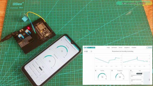
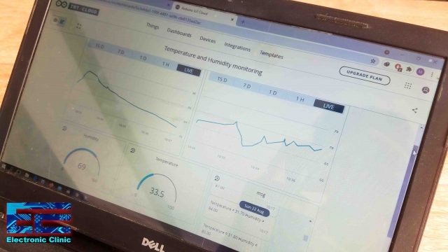
In this article, we are going to use Arduino IoT Cloud with the Nodemcu ESP8266. We will be using DHT11 temperature and Humidity module with the Nodemcu ESP8266. We will measure the Temperature and Humidity and then we will send these values to the Arduino IoT Cloud where these values will be displayed on the Gauges, charts, and message widgets. You can monitor these values using a dashboard on your cell phone or you can also use your computer or laptop. The dashboard which you can see on the cell phone is automatically generated and I have explained this in my previous tutorials. Anyways, with the help of this project you can monitor the temperature and humidity values from anywhere around the world if you have the internet connection. In this tutorial, I will also explain how to use the message widget on the Arduino IoT Cloud which you can use in different projects for displaying text messages.
In this tutorial, I will not explain the most basic things which I have already covered in my previous getting started tutorial, because the account registration and ArduinoCreateAgent installation is same for the ESP32 and Nodemcu ESP8266. Without any further delay, let’s get started!!!
Amazon Links:
DHT11 Temperature and Humidity Module:
Other Tools and Components:
Super Starter kit for Beginners
PCB small portable drill machines
*Please Note: These are affiliate links. I may make a commission if you buy the components through these links. I would appreciate your support in this way!
DHT11 Sensor:
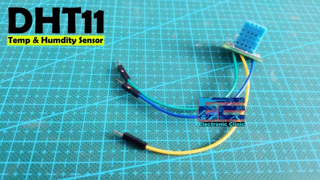
- DHT11 digital temperature and humidity sensor is a digital signal output with a calibrated temperature and humidity combined sensor.
- It uses a dedicated digital modules and acquisition of temperature and humidity sensor technology to ensure that products with high reliability and excellent long term stability.
- Sensor consists of a resistive element and a sense of wet NTC temperature measurement devices, and with a high-performance 8-bit microcontroller connected.
- The product has excellent quality, fast response, anti-interference ability, high cost and other advantages.
- The single-wire wiring scheme makes it easy to be integrated to other applications and the
simple communication protocol greatly reduces the programming effort required.
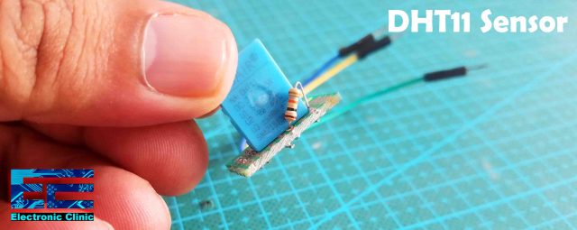
- For the easy interfacing I have already soldered some jumper wires.
This sensor module utilizes DHT11 as the sensitive component and has a bypass capacitor and a pull-up resistor on-board. The DHT11 is a pre-calibrated digital output temperature and humidity sensor. The single-wire wiring scheme makes it easy to be integrated to other applications. The simple communication protocol greatly reduces the programming effort required.
Specification:
Power supply voltage: 3.3~5.5V DC
Output: the single bus digital signal
Measuring range: 20-90%RH humidity, temperature 0~50°
The measurement accuracy of +-5%RH: humidity, temperature +-2 °
Resolution: 1%RH humidity, temperature 1 °
Exchangeability: fully interchangeable
Long term stability: < ± 1%RH
Size: 28 * 12 * 7.2mm
ESP8266 with DHT11, Circuit Diagram:
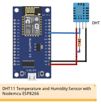
These are the minimal connections which you can start with if in case you want to use your laptop to power up the Nodemcu ESP8266, you can use these connections for testing your code. A 10K-ohm resistor is connected between the Data and VCC Pin. The data pin of the DHT11 Sensor is connected with the D4 pin of the Nodemcu ESP8266 WiFi Module. Now, let’s take a look at another circuit diagram.
External Power supply for ESP8266, DHT11, Circuit Diagram:
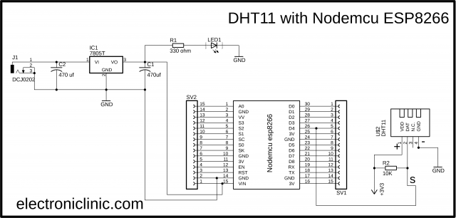
The DHT11 Temperature and Humidity sensor connection with the Nodemcu ESP8266 remain exactly the same. This time I added this 5V regulated power supply based on the 7805 voltage regulator and don’t forget to add these 470uF decoupling capacitors. You will need this 5v regulated power supply for the Nodemcu ESP8266 module because you cannot use your laptop or computer as the permanent power source.
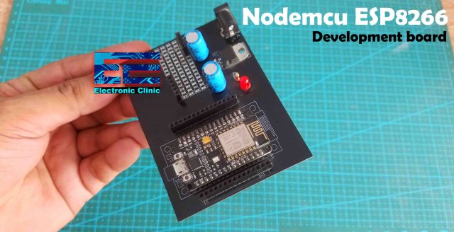
This is my Nodemcu ESP8266 development board based on the same connections as explained in the circuit diagram. I have already explained the designing and making.
I have also soldered a 10k-ohm resistor between the data and VCC pins.
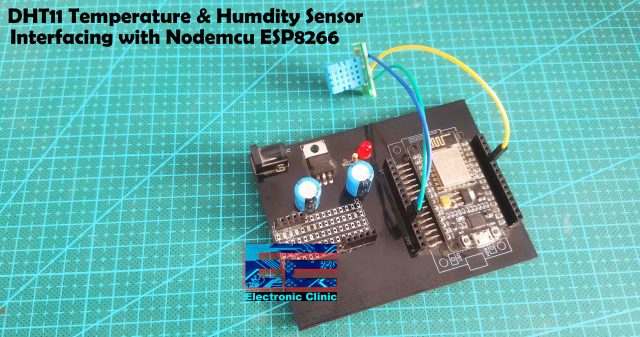
I connected the DHT11 Temperature and Humidity sensor with the Nodemcu ESP8266 as per the circuit diagram. Now, let’s start working on the Arduino IoT Cloud.
Arduino IoT Cloud Dashboard Designing:
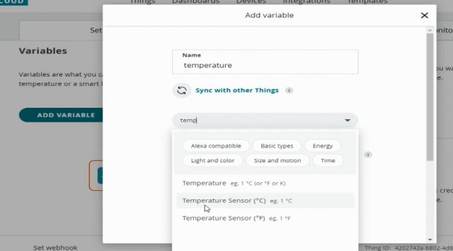
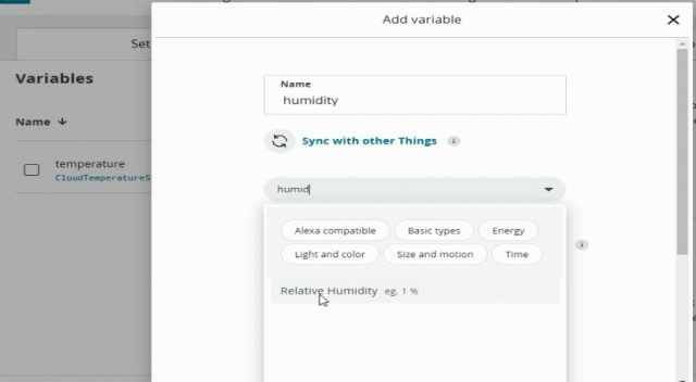
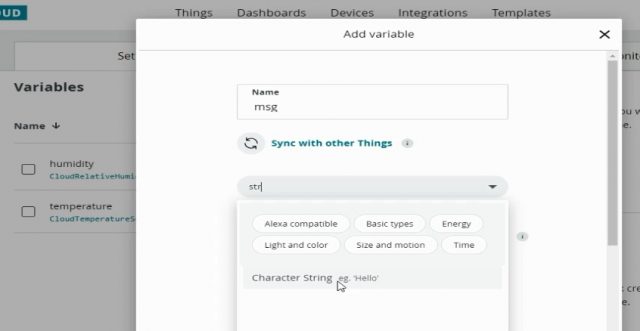
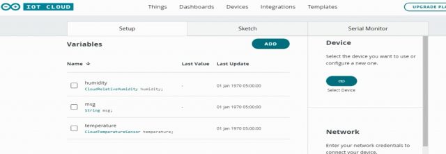
Now we will design application for the Temperature and Humidity monitoring system for which we will declare three variables. So, click on the add variable button and these variable will be:
- Temperature variable: it will be used for the measurement of the temperature we will select the variable type of the temperature sensor
- Humidity variable: now, we will add the humidity variable by selecting the variable type which is relative humidity and click on the add variable.
- Then we will add a string variable msg through which we will send data to messenger and will click on the add variable.
Now all the variables are declared and ready for use.
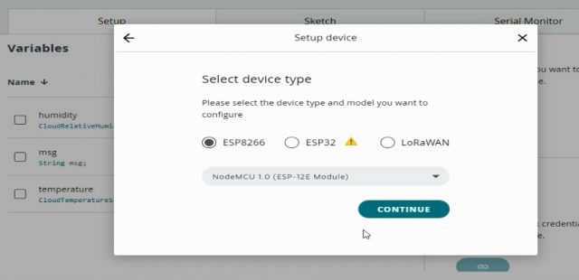
Now we will select the device; so click on the select device and then select the third party device and in the select type device we will select the ESP8266 and select NodeMCU 1.0 and click on the continue button.
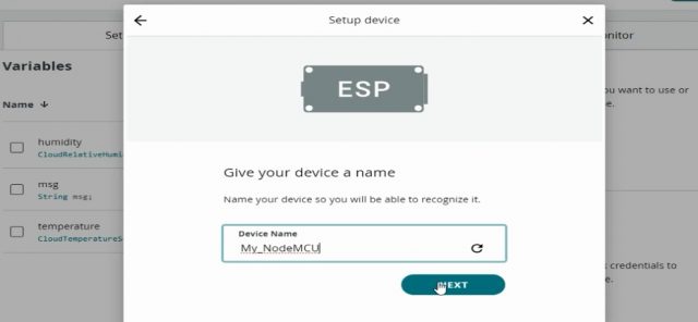
Then we will give a name to the device, in our case we are giving the name My_NodeMCU and click on the next button.
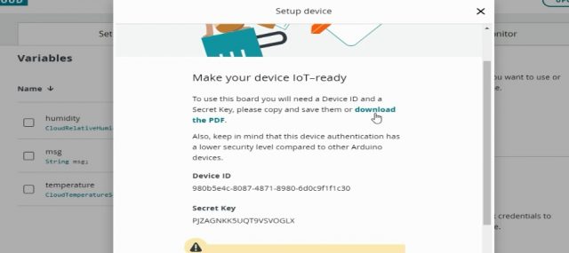
Now in order to make the device ready to use we will click on the download button and save the security id and secret key which will be used in the network connection.
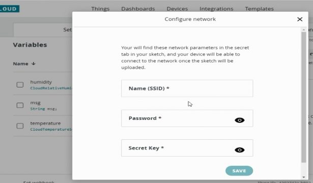
After that we will configure the network; so click on the network button, write the SSID which is the name of the Wifi which we are using and give the password and paste the secret key from the pdf file, and click on the Save button.
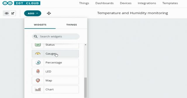
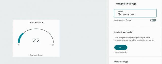
Now the network is successfully added and now we are ready to start working on the Dashboard. We will click on the dashboard in which we will design the application for the monitoring. First we will insert the gauge for the temperature.
Then we will link the temperature variable with the gauge.
So click the link variable and select the temperature.
In the similar way, we will add the humidity gauge and link the variable humidity with it.
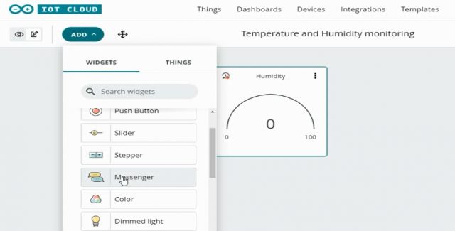
Now we will add the messenger through which we will receive the notification of temperature and humidity. So click on the add button and select the messenger.
Then we will link the string variable msg with it.
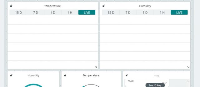
We have also added chart for both the humidity and temperature in order to monitor and temperature on daily and weekly basis, so we will click on the add button, select the chart for the temperature, and link it with the temperature variable; then we add another chart for the humidity and link it to the variable humidity.
After adding all the Widgets and linking all the variables the next step is to open the Arduino Online editor and start coding.
Arduino IoT cloud Dht11 Code:
|
1 2 3 4 5 6 7 8 9 10 11 12 13 14 15 16 17 18 19 20 21 22 23 24 25 26 27 28 29 30 31 32 33 34 35 36 37 38 39 40 41 42 43 44 45 46 47 48 49 50 51 52 53 54 55 56 57 58 59 60 61 62 63 64 65 66 67 68 69 70 |
Then we will click on the sketch to write the code we will add few lines to the code. /* Sketch generated by the Arduino IoT Cloud Thing "Temperature and humidity monitoring" https://create.arduino.cc/cloud/things/4202742a-b802-4d86-8f85-2a73394c0797 Arduino IoT Cloud Variables description The following variables are automatically generated and updated when changes are made to the Thing CloudRelativeHumidity humidity; String msg; CloudTemperatureSensor temperature; Variables which are marked as READ/WRITE in the Cloud Thing will also have functions which are called when their values are changed from the Dashboard. These functions are generated with the Thing and added at the end of this sketch. */ #include "thingProperties.h" #include "DHT.h" #define DHTpin 2 // D4 on the nodemcu ESP8266 #define DHTTYPE DHT11 DHT dht(DHTpin,DHTTYPE); void setup() { // Initialize serial and wait for port to open: Serial.begin(9600); // This delay gives the chance to wait for a Serial Monitor without blocking if none is found delay(1500); // Defined in thingProperties.h initProperties(); // Connect to Arduino IoT Cloud ArduinoCloud.begin(ArduinoIoTPreferredConnection); /* The following function allows you to obtain more information related to the state of network and IoT Cloud connection and errors the higher number the more granular information you’ll get. The default is 0 (only errors). Maximum is 4 */ setDebugMessageLevel(2); ArduinoCloud.printDebugInfo(); } void loop() { ArduinoCloud.update(); // Your code here dht_sensor_getdata(); } void onHumidityChange() { // Do something } void onMsgChange() { // Do something } void dht_sensor_getdata() { float hm= dht.readHumidity(); Serial.print("Humidity "); Serial.println(hm); float temp=dht.readTemperature(); Serial.print("Temperature "); Serial.println(temp); humidity=hm; temperature=temp; msg="Temperature = " + String (temperature)+" Humidity = " + String(humidity); } |
Nodemcu ESP8266 and DHT11, Code Explanation:
|
1 |
#include "thingProperties.h" |
This Header file is automatically added.
#include “DHT.h”
I only added the DHT.h header file. You don’t need to download this header file, as we are using the Arduino Online editor so most of the libraries are already added. This is an amazing thing, as most of the beginners find it quite hard to download and install libraries. So, with the Arduino Online editor you only need to add this line of code and that’s it.
|
1 2 3 4 5 6 7 8 9 10 11 12 13 |
#define DHTpin 2 // D4 on the nodemcu ESP8266 #define DHTTYPE DHT11 DHT dht(DHTpin,DHTTYPE); void setup() { Serial.begin(9600); delay(1500); initProperties(); ArduinoCloud.begin(ArduinoIoTPreferredConnection); setDebugMessageLevel(2); ArduinoCloud.printDebugInfo(); } |
Inside the setup() function, I activated the Serial Communication which I used for debugging purposes to check my code if it’s working. The other lines of code inside the setup() function are automatically added.
|
1 2 3 4 5 |
void loop() { ArduinoCloud.update(); // Your code here dht_sensor_getdata(); } |
Inside the loop() function, the ArduinoCloud.update() is automatically added. I added this dht_sensor_getdata() function, which is a user-defined function. I have placed my DHT11 sensor code inside this function.
|
1 2 3 4 5 6 7 8 |
void onHumidityChange() { // Do something } void onMsgChange() { // Do something } |
I didn’t use the functions which were automatically generated.
|
1 2 3 4 5 6 7 8 9 10 11 12 13 |
void dht_sensor_getdata() { float hm= dht.readHumidity(); Serial.print("Humidity "); Serial.println(hm); float temp=dht.readTemperature(); Serial.print("Temperature "); Serial.println(temp); humidity=hm; temperature=temp; msg="Temperature = " + String (temperature)+" Humidity = " + String(humidity); } |
But I defined my own function dht_sensor_getdata(). This is a user-defined function, it has no return type, and does not take any arguments as the input. Inside this function, we are simply reading the humidity and temperature values which are stored in variables humidity and temperature and then we send these values to the Arduino IoT Cloud where these values are displayed on the Gauges and charts widgets. The msg variable is also automatically generated and this variable is used to send a string message to the Arduino IoT cloud Dashboard.
|
1 2 3 |
CloudRelativeHumidity humidity; String msg; CloudTemperatureSensor temperature; |
You can find all the automatically generated variables on the top of the sketch, so you have to use these variables to send your sensors data to the Arduino IoT Cloud. So, that’s all about the programming.
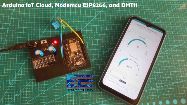
I successfully monitored the Humidity and Temperature values on my cell phone and also on my Laptop screen.
For the practical demonstration and set by step explanation watch video tutorial given below.
Video tutorial:




Excellent and brilliant way of explaining the concepts.