Automatic Speed Controller for Electric Bike using Arduino and Gyroscope mpu6050
Last Updated on May 10, 2026 by Engr. Shahzada Fahad
Table of Contents
Electric Bike Automatic Speed Controller Description:
Automatic Speed Controller for Electric Bike using Arduino and Gyroscope mpu6050-In my previous tutorials, I explained how to convert an old bicycle into a Hybrid electric bike. In part1 of the Hybrid electric bike, I explained all the basics, including the wheel Hub selection, Motor installation, and basic testing.
While in part2 I explained how to make your own electric bike motor controller using mc33151 dual Mosfets driver IC, 80NF70 high ampere Mosfets, a potentiometer, and Arduino. I highly recommend first, you should watch part1 and part2 of the hybrid electric bike and then you can resume from here.
In today’s article, which is part3 of the hybrid Electric Bike, we are going to control the speed of electric bike automatically using the GY-521 MPU6050 six degrees of freedom 3-Axis Gyroscope and Accelerometer Module. The MPU6050 Module can be fixed on the Helmet or on the jacket and then depending on the angle the speed can be increased or decreased automatically. For the practical demonstration watch video given at the end of this article.
Remember? In part2 I used the variable resistor for controlling the speed, in part 3 that variable resistor is used to activate and deactivate the automatic speed control system. When the value is less than 100 the automatic speed control system is deactivated. When the value is greater than 100 then the automatic speed control system is activated and the MPU6050 Module can be used to control the speed. if you want to display the mpu6050 data on 16×2 i2c LCD and ssd1306 OLED display then check out this article.
In this article, I will cover,
- Complete circuit diagram explanation
- Arduino program explanation and finally
- testing
Without any further delay let’s get started!!!
If in case you want to check my latest work on
Salvage Hoverboard Motors from a dead Hoverboard
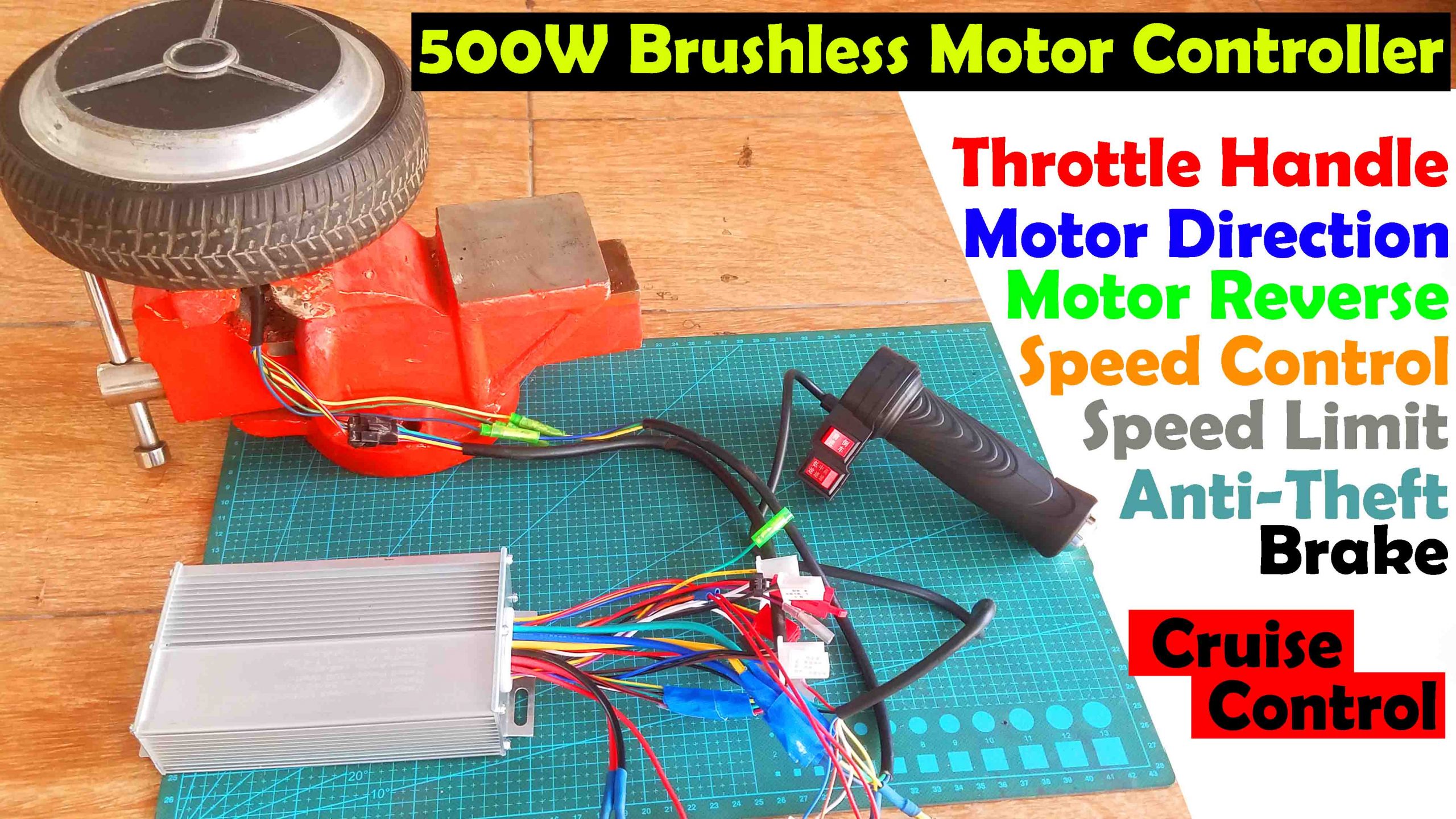
500 watts Ebike BLDC Motor Wiring
How to make a Trike Electric Scooter using Hoverboard motors and 500 Watt Motor controllers
Amazon Purchase links :
500 Watt 24v Electric bike Motor:
Double sprocket Gear wheel Hub:
12v 12AH Rechargeable Battery:
PCB screw Terminal block connector:
Disclosure: These are affiliate links. As an Amazon Associate I earn from qualifying purchases.
GY-521 MPU6050 Gyroscope Module:


This is the GY-521 MPU6050 6DOF 3-Axis Gyroscope and Accelerometer Module. The MPU6050 communicates with the Arduino through the I2C protocol. The MPU6050 always acts as a slave to the Arduino with the SDA and SCL pins connected to the I2C bus. This module needs 3 to 5 volts. This Module can be used in a hand gesture controlled Robot, wheelchair, earthquake detection system, Self-balancing Robot, a self-balancing platform for a camera, Segway, etc.
As you can see clearly this module has a total of 8 Pins which are clearly labeled. Out of these 8 pins I will be using only the VCC, GND, SCL, SDA, and INT.

Now you can see the MPU6050 Sensor is sandwiched between the Vero Boards and now it’s really easy to handle.
Automatic Speed Controller Electric bike Motor Driver Circuit Diagram:
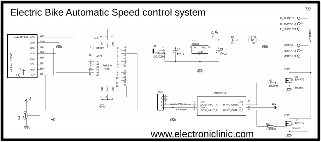
This schematic is designed in the Cadsoft Eagle 9.1.0 version. If you want to learn how to make a schematic and PCB, then watch my Tutorial, the link is given in the description.
The circuit diagram is very simple, as you can see VCC is connected with 3.3 volts, GND is connected with the GND, SCL and SDA are connected with the Arduino’s Analog pins A5 and A4, while the INT pin of the MPU6050 module is connected with pin number 2 of the Arduino.
Download MPU6050 Library for eagle.
A variable resistor is connected with the Analog pin A0 of the Arduino. while the other two legs of the variable resistor are connected with the Arduino’s 5v and Ground.
The MC33151 Eagle library can be downloaded from my website. First, let’s start with the Power Supply.
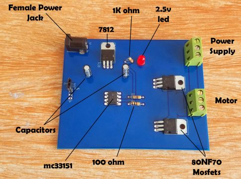
This Power Supply is based on the famous LM7812 voltage regulator. J1 is the female power jack and this is where we connect 12 volts from the battery or solar panel. Two 470uf capacitors are connected at the input and output of the voltage regulator. 1 kilo-ohm resistor is connected in series with the 2.5v led. This is a current limiting resistor. the output of this voltage regulator is connected with the VCC pin of the MC33151 MOSFETs driver.
Pin number 2 and pin 4 which are the logic input A and logic input B are connected together and connected with the Arduino’s pin number 3 which is the PWM pin. Pin number 5 and pin number 7 are used to control the MOSFETs. As you can see the Drains are connected together and the sources of both the MOSFETs are also connected together.
With motor-1 and motor-3 we connect the motor while with E_Supply-1 and E_Supply-3 we connect the 12volts. Before making the PCB I checked this circuit on a Vero board, and performed all the tests, after I was satisfied with the result, then I designed a PCB, generated the Gerber files and placed an online order on the NextPCB official website.
Download Gerber files: electric bike gerber files
Download Eagle PCB Board File: arduino motor driver
Download the mc33151 eagle library:
The online order placement on NextPCB official website, Soldering, and interfacing is already explained in part2 of the Hybrid Electric Bike. The video is given above.
Interfacing:

All the connections explained in part2 remain the same, this time I only added the MPU6050 module. The VCC of the MPU6050 Module is connected with the Arduino’s 3.3 volts; the ground is connected with the GND. While the SDA and SCL pins of the MPU6050 are connected with the Arduino’s A4 and A5 pins; as per the circuit diagram already explained.
Automatic Speed Controller Arduino Programming for E-Bike:
Before you start the programming, first of all, make sure that you download these Libraries..
|
1 2 3 4 5 6 7 8 9 10 11 12 13 14 15 16 17 18 19 20 21 22 23 24 25 26 27 28 29 30 31 32 33 34 35 36 37 38 39 40 41 42 43 44 45 46 47 48 49 50 51 52 53 54 55 56 57 58 59 60 61 62 63 64 65 66 67 68 69 70 71 72 73 74 75 76 77 78 79 80 81 82 83 84 85 86 87 88 89 |
/* vcc = 3.3v Gnd = gnd int = 2 scl = a5 sda = a4 */ #include "Wire.h" #include "I2Cdev.h" #include "MPU6050.h" MPU6050 mpu; int PWMV = 3; int resistor = A0; int flag = 0; int16_t ax, ay, az; int16_t gx, gy, gz; int val; int prevVal; int valax; int valay; int valaz; void setup() { Wire.begin(); Serial.begin(38400); pinMode(PWMV, OUTPUT); pinMode(resistor, INPUT); Serial.println("Initialize MPU"); mpu.initialize(); Serial.println(mpu.testConnection() ? "Connected" : "Connection failed"); } void loop() { int data = analogRead(resistor); mpu.getMotion6(&ax, &ay, &az, &gx, &gy, &gz); valax = map(ax, -17000, 17000, 0, 255) ; valay = map(ay, -17000, 17000, 0, 255); valaz = map(az, -17000, 17000, 0, 255); Serial.println("az: "); Serial.println(valaz); if(data < 100) { flag = 0; analogWrite(PWMV, 255); delay(10); } if(data >= 100) { flag = 1; } if ( flag == 1) { if( valaz < 130) analogWrite(PWMV, 255); if ((valaz > 130)&&(valaz <= 150)) analogWrite(PWMV, 250); if ((valaz > 150)&&(valaz <= 170)) analogWrite(PWMV, 200); if ((valaz > 170)&&(valaz <= 190)) analogWrite(PWMV, 150); if ((valaz > 190)&&(valaz <= 210)) analogWrite(PWMV, 100); if (valaz > 210) analogWrite(PWMV, 50); delay(10); } } |
Automatic Speed Controller Program Explanation:
The MPU6050 GY-521 module can be powered up using 3.3 to 5 Volts. The INT pin is connected with the Arduino’s Pin number 2; the SCL Pin is connected with the Analog Pin A5 while the SDA Pin is connected with the Analog Pin A4 of the Arduino.
The logic input A and logic input B pins of the Mosfets driver are connected with the Arduino’s pin number 3 which is the PWM pin.
A Variable resistor is connected with the Analog pin A0.
The variable flag of the type integer is used to activate and deactivate the automatic speed control system.
In the void setup function, I activated the i2c bus and also activated the serial communication using the Serial.begin function. 38400 is the baud rate.
Pwmv is set as the output while the resistor is set as the input.
In the void loop function, we simply read the variable resistor and store the value in variable data.
Then using these if conditions, we check whether the value of the variable resistor is less than 100 or greater than 100. If the value is less than 100 then flag = 0 and stops the electric bike motor.
If the value is greater than 100 then flag = 1, which means to activate the speed control system
These conditions are used to check the angle of the mpu6050 and then accordingly control the speed of the electric bike motor. So that’s all about the programming.
For the Practical demonstration and step by step explanation watch video tutorial given below.
Watch Video Tutorial:
Discover more from Electronic Clinic
Subscribe to get the latest posts sent to your email.


Superb idea
Is it possible to apply a 48v voltage instead of 12v with the same circuit? If not, how should it be changed in order to work with 48v?
Thanks in advance
Best regards
Matteo