IOT based Car Parking System using Arduino and Nodemcu esp8266
Last Updated on August 18, 2024 by Engr. Shahzada Fahad
Table of Contents
IoT Car Parking System:
IoT based car parking Monitoring system- In this tutorial, you will learn how to make an IOT based Car Parking Slots monitoring system using Arduino, Nodemcu esp8266 wifi module, and Blynk application. With the help of the Nodemcu esp8266 wifi module and Blynk application, the parking slots can be monitored from anywhere around the world. In this Tutorial, you will also learn how to use the tabs and led widgets in the Blynk application.
The Parking Area is divided into two Parkings.
- Parking 1
- Parking 2
Each Parking has 3 Slots and every slot has one infrared sensor. So we have a total of 6 infrared sensors. Each sensor is used to detect the presence of Car in the Slot. These infrared sensors are connected with the Arduino. So when a car is parked in the slot, the Arduino sends a command to the Nodemcu esp8266 wifi module, then Nodemcu then sends the command to the Blynk application.
Amazon Links:
Arduino Nano USB-C Type (Recommended)
*Disclosure: These are affiliate links. As an Amazon Associate I earn from qualifying purchases.
About the IR Sensor Module:
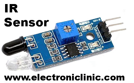
This is the IR sensor which I will be using for the cars detection. As you can see the three male headers are clearly labeled with the VCC, GND, and OUT. The VCC pin is connected with the Arduino’s 5 volts. The ground is connected with the Arduion’s ground. While the OUT pin is connected with Arduino’s IO pins. which I will explain in the circuit diagram. While the black and white LEDs are the IR LEDs “one is the Tx while the other one is the Rx”.
About the Nodemcu ESP8266 WIFI Module:
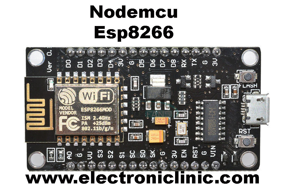
This is the Nodemcu ESP8266 wifi module, with the help of this module we can monitor the car parking slots from anywhere around the world. As you can see clearly all the pins are clearly labeled. Never power up the Nodemcu esp8266 wifi module using the Arduino’s 5 volts. If you power up this module using the Arduino’s 5 volts then this wifi module we will keep resetting. To solve this problem you can design a separate power supply of this module using the LM7805 voltage regulator.
IoT based car parking Circuit Diagram:
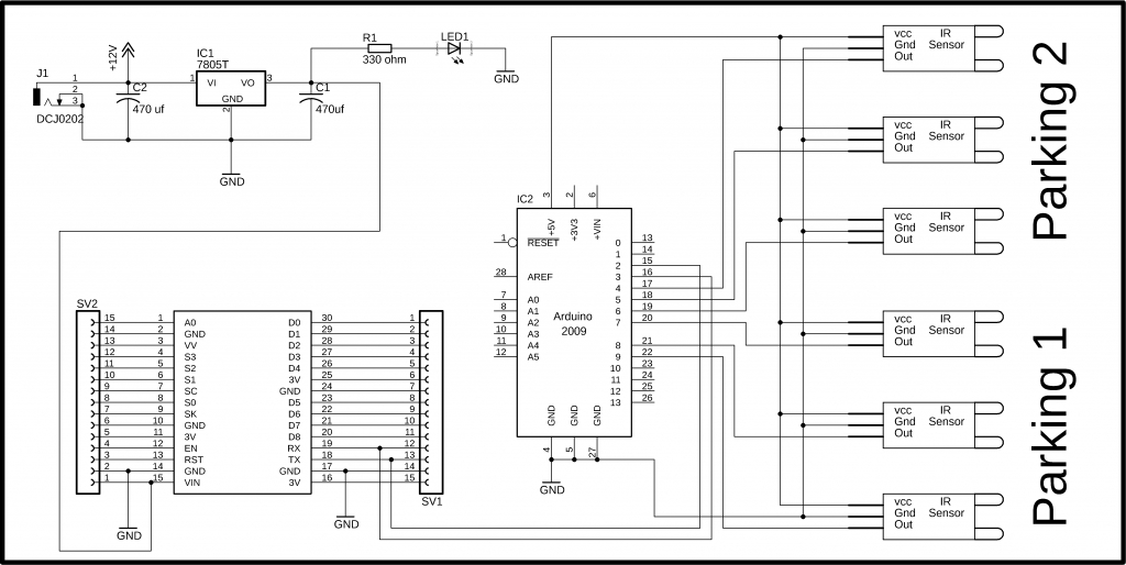
As you can see six infrared sensors are connected with the Arduino pins 4 to 9. The infrared sensor VCC pins are connected with the Arduino’s 5v. Grounds are connected with the Arduino’s Ground while the out pins of all the infrared sensors are connected with pin 4 to 9.
The Nodemcu module tx and Rx pins are connected with pin2 and pin3 of the Arduino. while the Vin pin of the Nodemcu module is connected with the output of the voltage regulator. This is a regulated 5v power supply based on the lm7805 voltage regulator.
Two 470uf capacitors are connected at the input and output side of the regulator. A 330-ohm resistor is connected in series with a 2.5v led. This is a current limiting resistor. While J1 is a dc female socket, over here you can connect a 12v adaptor or battery. But you can also power up the Nodemcu module using your laptop USB port. I will be using two USB cables, I cable will be used for powering up the Arduino and the other USB cable will be used to power up the Nodemcu.
Note: this old version of the Blynk app is no more functional. For the blynk mobile App setup and Blynk.cloud dashboard setup ready my article on the New Blynk V2.0. In this article I have explained how to migrate your projects from Blynk 1.0 to the new Blynk V2.0. You can also watch the video.
Blynk Application of IoT based car parking:
For the android or apple cell phone application designing you will need to download the Blynk application from the App Store. After you download the Blynk application then you will need to register yourself for free using Facebook or any other email id. The cell phone application making is explained in the video. The video is available at the end of this Article.
Programming of IoT based car parking:
In this project, two programs are used one for the Arduino and another one for the Nodemcu esp8266 wifi module.
Car Parking Arduino Programming:
|
1 2 3 4 5 6 7 8 9 10 11 12 13 14 15 16 17 18 19 20 21 22 23 24 25 26 27 28 29 30 31 32 33 34 35 36 37 38 39 40 41 42 43 44 45 46 47 48 49 50 51 52 53 54 55 56 57 58 59 60 61 62 63 64 65 66 67 68 69 70 71 72 73 74 75 76 77 78 79 80 81 82 83 84 85 86 87 88 89 90 91 92 93 94 95 96 97 98 99 100 101 102 103 104 105 106 107 108 109 110 111 112 113 114 115 116 117 118 119 120 121 122 123 124 125 126 127 128 129 130 131 132 133 134 135 136 137 138 139 140 141 142 143 144 145 146 147 |
#include <SoftwareSerial.h> SoftwareSerial nodemcu(2,3); int parking1_slot1_ir_s = 4; // parking slot1 infrared sensor connected with pin number 4 of arduino int parking1_slot2_ir_s = 5; int parking1_slot3_ir_s = 6; int parking2_slot1_ir_s = 7; int parking2_slot2_ir_s = 8; int parking2_slot3_ir_s = 9; String sensor1; String sensor2; String sensor3; String sensor4; String sensor5; String sensor6; String cdata =""; // complete data, consisting of sensors values void setup() { Serial.begin(9600); nodemcu.begin(9600); pinMode(parking1_slot1_ir_s, INPUT); pinMode(parking1_slot2_ir_s, INPUT); pinMode(parking1_slot3_ir_s, INPUT); pinMode(parking2_slot1_ir_s, INPUT); pinMode(parking2_slot2_ir_s, INPUT); pinMode(parking2_slot3_ir_s, INPUT); } void loop() { p1slot1(); p1slot2(); p1slot3(); p2slot1(); p2slot2(); p2slot3(); cdata = cdata + sensor1 +"," + sensor2 + ","+ sensor3 +","+ sensor4 + "," + sensor5 + "," + sensor6 +","; // comma will be used a delimeter Serial.println(cdata); nodemcu.println(cdata); delay(6000); // 100 milli seconds cdata = ""; digitalWrite(parking1_slot1_ir_s, HIGH); digitalWrite(parking1_slot2_ir_s, HIGH); digitalWrite(parking1_slot3_ir_s, HIGH); digitalWrite(parking2_slot1_ir_s, HIGH); digitalWrite(parking2_slot2_ir_s, HIGH); digitalWrite(parking2_slot3_ir_s, HIGH); } void p1slot1() // parkng 1 slot1 { if( digitalRead(parking1_slot1_ir_s) == LOW) { sensor1 = "255"; delay(200); } if( digitalRead(parking1_slot1_ir_s) == HIGH) { sensor1 = "0"; delay(200); } } void p1slot2() // parking 1 slot2 { if( digitalRead(parking1_slot2_ir_s) == LOW) { sensor2 = "255"; delay(200); } if( digitalRead(parking1_slot2_ir_s) == HIGH) { sensor2 = "0"; delay(200); } } void p1slot3() // parking 1 slot3 { if( digitalRead(parking1_slot3_ir_s) == LOW) { sensor3 = "255"; delay(200); } if( digitalRead(parking1_slot3_ir_s) == HIGH) { sensor3 = "0"; delay(200); } } // now for parking 2 void p2slot1() // parking 1 slot3 { if( digitalRead(parking2_slot1_ir_s) == LOW) { sensor4 = "255"; delay(200); } if( digitalRead(parking2_slot1_ir_s) == HIGH) { sensor4 = "0"; delay(200); } } void p2slot2() // parking 1 slot3 { if( digitalRead(parking2_slot2_ir_s) == LOW) { sensor5 = "255"; delay(200); } if( digitalRead(parking2_slot2_ir_s) == HIGH) { sensor5 = "0"; delay(200); } } void p2slot3() // parking 1 slot3 { if( digitalRead(parking2_slot3_ir_s) == LOW) { sensor6 = "255"; delay(200); } if( digitalRead(parking2_slot3_ir_s) == HIGH) { sensor6 = "0"; delay(200); } } |
Nodemcu esp8266 wifi module Programming of IoT based car parking:
|
1 2 3 4 5 6 7 8 9 10 11 12 13 14 15 16 17 18 19 20 21 22 23 24 25 26 27 28 29 30 31 32 33 34 35 36 37 38 39 40 41 42 43 44 45 46 47 48 49 50 51 52 53 54 55 56 57 58 59 60 61 62 63 64 65 66 67 68 69 70 71 72 73 74 75 76 77 78 79 80 81 82 83 84 85 86 87 88 89 90 91 92 93 94 95 96 97 98 99 100 101 102 103 104 105 106 107 108 109 110 111 112 113 114 115 116 117 118 119 120 121 122 123 124 125 126 127 128 129 130 131 132 133 134 135 136 137 138 139 140 141 142 143 144 145 146 147 148 149 150 151 152 153 154 155 156 |
#define BLYNK_PRINT Serial #include <ESP8266WiFi.h> #include <BlynkSimpleEsp8266.h> #include <SoftwareSerial.h> #include <SimpleTimer.h> char auth[] = "ac173b0527c94a91a6cde0dcdfe6bdef"; // Your WiFi credentials. // Set password to "" for open networks. char ssid[] = "ZONG MBB-E8231-6E63"; char pass[] = "08659650"; SimpleTimer timer; String myString; // complete message from arduino, which consistors of snesors data char rdata; // received charactors int firstVal, secondVal,thirdVal; // sensors int led1,led2,led3,led4,led5,led6; // This function sends Arduino's up time every second to Virtual Pin (1). // In the app, Widget's reading frequency should be set to PUSH. This means // that you define how often to send data to Blynk App. void myTimerEvent() { // You can send any value at any time. // Please don't send more that 10 values per second. Blynk.virtualWrite(V1, millis() / 1000); } void setup() { // Debug console Serial.begin(9600); Blynk.begin(auth, ssid, pass); timer.setInterval(1000L,sensorvalue1); timer.setInterval(1000L,sensorvalue2); timer.setInterval(1000L,sensorvalue3); timer.setInterval(1000L,sensorvalue4); timer.setInterval(1000L,sensorvalue5); timer.setInterval(1000L,sensorvalue6); } void loop() { if (Serial.available() == 0 ) { Blynk.run(); timer.run(); // Initiates BlynkTimer } if (Serial.available() > 0 ) { rdata = Serial.read(); myString = myString+ rdata; // Serial.print(rdata); if( rdata == '\n') { Serial.println(myString); // Serial.println("fahad"); // new code String l = getValue(myString, ',', 0); String m = getValue(myString, ',', 1); String n = getValue(myString, ',', 2); String o = getValue(myString, ',', 3); String p = getValue(myString, ',', 4); String q = getValue(myString, ',', 5); // these leds represents the leds used in Blynk application led1 = l.toInt(); led2 = m.toInt(); led3 = n.toInt(); led4 = o.toInt(); led5 = p.toInt(); led6 = q.toInt(); myString = ""; // end new code } } } void sensorvalue1() { int sdata = led1; // You can send any value at any time. // Please don't send more that 10 values per second. Blynk.virtualWrite(V10, sdata); } void sensorvalue2() { int sdata = led2; // You can send any value at any time. // Please don't send more that 10 values per second. Blynk.virtualWrite(V11, sdata); } void sensorvalue3() { int sdata = led3; // You can send any value at any time. // Please don't send more that 10 values per second. Blynk.virtualWrite(V12, sdata); } void sensorvalue4() { int sdata = led4; // You can send any value at any time. // Please don't send more that 10 values per second. Blynk.virtualWrite(V13, sdata); } void sensorvalue5() { int sdata = led5; // You can send any value at any time. // Please don't send more that 10 values per second. Blynk.virtualWrite(V14, sdata); } void sensorvalue6() { int sdata = led6; // You can send any value at any time. // Please don't send more that 10 values per second. Blynk.virtualWrite(V15, sdata); } String getValue(String data, char separator, int index) { int found = 0; int strIndex[] = { 0, -1 }; int maxIndex = data.length() - 1; for (int i = 0; i <= maxIndex && found <= index; i++) { if (data.charAt(i) == separator || i == maxIndex) { found++; strIndex[0] = strIndex[1] + 1; strIndex[1] = (i == maxIndex) ? i+1 : i; } } return found > index ? data.substring(strIndex[0], strIndex[1]) : ""; } |
Watch Video Tutorial:
Discover more from Electronic Clinic
Subscribe to get the latest posts sent to your email.


Can the same thing be done on the thingspeak server instead of the app
why you need arduino? NodeMCU has digital IO too.
Nodemcu esp8266 wifi module Programming of iot based car parking there is some error coming during verify on IDE platform. can anyone help me.
in list component why use MEGA2560 ? in the video it doesn’t exist mega2560
arduino mega can also be used in this project. it gives you more i/o pins, more serial ports. these are some of the most commonly used components and tools.
are the above components are all needed for this project?? because you didnt use any led screen in the video
Not all the components are used, some tools and components which I have added are the most commonly used components, which often people need. You can purchase the components which are used in the circuit diagram.
i tried to run ur given nodemcu program but im getting an error. i posted it in Blynk community i got a reply ”The Blynk library includes Blunk timer, which is a improved version of simpletimer try removing the #include <simpletimer.h> and replacing SimpleTimer timer; with BlynkTimer timer;”
After changing this program error was solved but another problem i got is The slot is continuously blinking. The IR sensor is working is also working fine when i move object towards it ir led glows and vice versa. so what may be the problem
Arduino: 1.8.12 (Windows 10), Board: “NodeMCU 1.0 (ESP-12E Module), 80 MHz, Flash, Legacy (new can return nullptr), All SSL ciphers (most compatible), 4MB (FS:2MB OTA:~1019KB), 2, v2 Lower Memory, Disabled, None, Only Sketch, 115200”
In file included from C:\Program Files (x86)\Arduino\libraries\Blynk\src/Blynk/BlynkApi.h:17:0,
C:\Program Files (x86)\Arduino\libraries\Blynk\src/Blynk/BlynkTimer.h:36:21: error: redefinition of ‘class BlynkTimer’
#define SimpleTimer BlynkTimer
C:\Users\HP\Documents\Arduino\libraries\SimpleTimer/SimpleTimer.h:10:7: note: in expansion of macro ‘SimpleTimer’
class SimpleTimer {
C:\Program Files (x86)\Arduino\libraries\Blynk\src/Blynk/BlynkTimer.h:36:21: error: previous definition of ‘class BlynkTimer’
#define SimpleTimer BlynkTimer
C:\Program Files (x86)\Arduino\libraries\Blynk\src/Blynk/BlynkTimer.h:41:7: note: in expansion of macro ‘SimpleTimer’
class SimpleTimer {
exit status 1
Error compiling for board NodeMCU 1.0 (ESP-12E Module).
This report would have more information with
“Show verbose output during compilation”
option enabled in File -> Preferences.
Did you fix it, can you show me?
Dude please tell me which version of simpletimer and blynk libraries. Also please tell me how to solve this below error, also I have compiled the exactly same program as you given:
ERROR:
In file included from C:\Users\Dell E7440\Documents\Arduino\libraries\Blynk\src/Blynk/BlynkApi.h:17:0,
C:\Users\Dell E7440\Documents\Arduino\libraries\Blynk\src/Blynk/BlynkTimer.h:34:21: error: redefinition of ‘class BlynkTimer’
#define SimpleTimer BlynkTimer
C:\Users\Dell E7440\Documents\Arduino\libraries\SimpleTimer/SimpleTimer.h:10:7: note: in expansion of macro ‘SimpleTimer’
class SimpleTimer {
C:\Users\Dell E7440\Documents\Arduino\libraries\Blynk\src/Blynk/BlynkTimer.h:34:21: error: previous definition of ‘class BlynkTimer’
#define SimpleTimer BlynkTimer
C:\Users\Dell E7440\Documents\Arduino\libraries\Blynk\src/Blynk/BlynkTimer.h:38:7: note: in expansion of macro ‘SimpleTimer’
class SimpleTimer {
exit status 1
Error compiling for board NodeMCU 1.0 (ESP-12E Module).
can you please add to the circuit LCD and two gates one for entry and exit gate… I want to make same project with adding the two gates and lcd display 16×2. waiting for your answer thank you,
Hello guys, can you explain me please what is sv1 and sv2 ? And if you can send my a photo with the final conections ?
can you add here all libraries
I am trying to do this using a Bluetooth but it’s not connecting with blynk app properly
I need to replace this line nodemac.println(cdata);
What do I do for Bluetooth
Hello, can you help me to implement this project, but with the firebase instead blynk ? I will really appreciate, you will help me a lot ! Thanks!
How can we implement this for more than 20 sensors? The arduino has only 14 digital inputs. Could you please suggest an alternative.
Brother I need old account this version needs upgrade don’t have enough money needed urgently tomorrow have to submit project