IoT Lithium Battery Monitoring system using ESP8266 & Arduino IoT Cloud
Last Updated on September 17, 2024 by Engr. Shahzada Fahad
Table of Contents
IoT Lithium Battery monitoring system, Overview:
IoT Lithium Battery Monitoring System using Nodemcu ESP8266 and Arduino IoT Cloud– In this tutorial we are going to make an IoT battery monitoring system for the Lithium ion battery using Arduino IoT Cloud and Nodemcu ESP8266 WiFi module. We will display the battery voltage and battery percentage on gauges and charts. Previously, I designed a battery monitoring system for a 12V Lead Acid battery and I used Blynk application for the remote monitoring over WiFi.
In this tutorial, I will be using the Arduino IoT Cloud which is becoming very popular and I have already used in a couple of projects. If you are a beginner then I highly recommend read my getting started tutorial on the Arduino IoT Cloud.
Amazon Links:
Disclosure: These are affiliate links. As an Amazon Associate I earn from qualifying purchases.
Lithium Ion Battery Monitoring Circuit diagram:
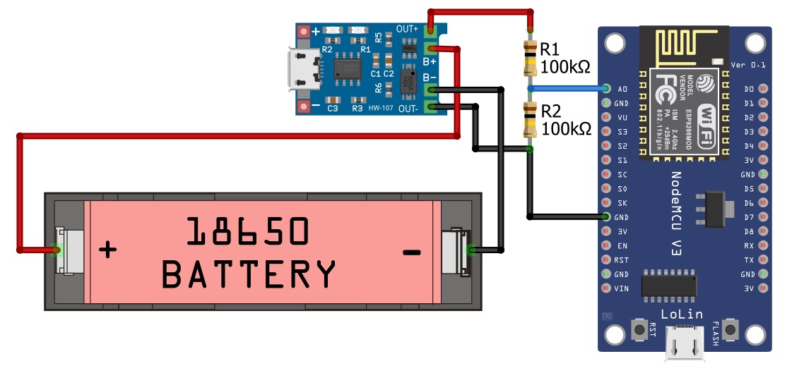
First of all, we will design circuit diagram for which we will require the following components:
- NodeMCU ESP8266
- TP4056 battery module
- Lithium ion battery
- Two 100 KΩ resistor
First of all, we will make a voltage divider circuit by connecting the 100k resistors in series and connect the A0 pin of the Nodemcu ESP8266 between the two resistors. Then connect one end of the resistor with the OUT+ of the TP4056 battery module and connect the other end of the resistor with the OUT- of the TP4056 module. Then connect the B+ of the TP4056 module with the positive terminal of the battery and B- of the TP4056 module with the negative terminal of the battery.
Designing IOT application for battery monitoring system:
Now, in order to create battery monitoring system, we will go to the Arduino official website.
https://create.arduino.cc/
Now, if you do not have an account first of all create account on the Arduino cc which we have already discussed in the getting started tutorial on the Arduino IoT Cloud.
If you already have an account then you are all set and if not then follow the steps given below.
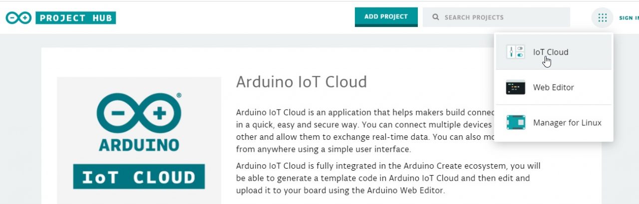
Click on the IOT cloud.
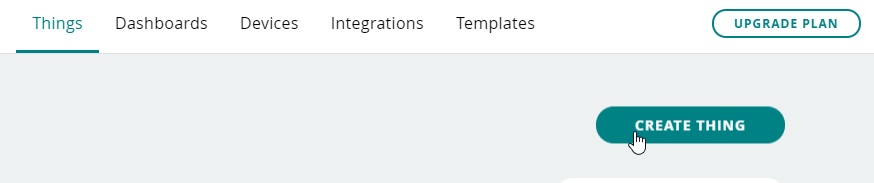
Now click on the CREATE THING
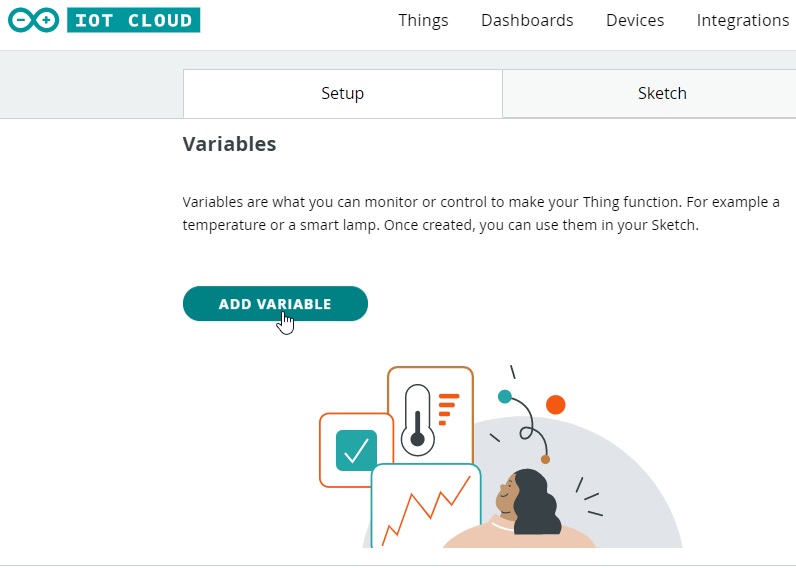
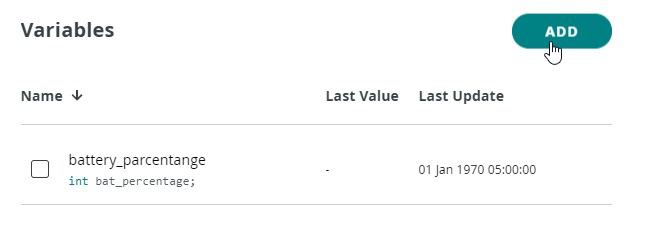
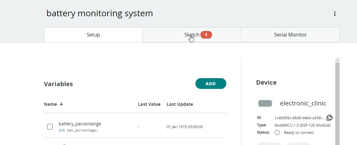
Now, we will create variables, in our case we are using two variables; one for the battery percentage and the other one for the battery voltage. So to add the variables click on the ADD VARIABLE button.
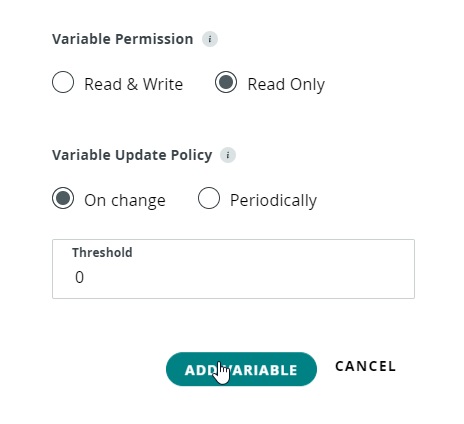
When we click on the ADD VARIABLE button, a dialog box will open in which we will define the type, name, and variable permission. In the first variable, we will store the percentage of the battery for which we declare the integer variable and as we are going to only read the data, so we will select the read only.
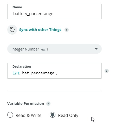
In the variable update policy, we will select the on change and click on the add variable.
Now, we will create another variable for the battery voltage; so, now we will click on the add button to add another variable.
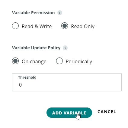
Now, we will give the name voltage to the variable and declare it as the float type and in this case again we are only reading the data so we will select the read only.
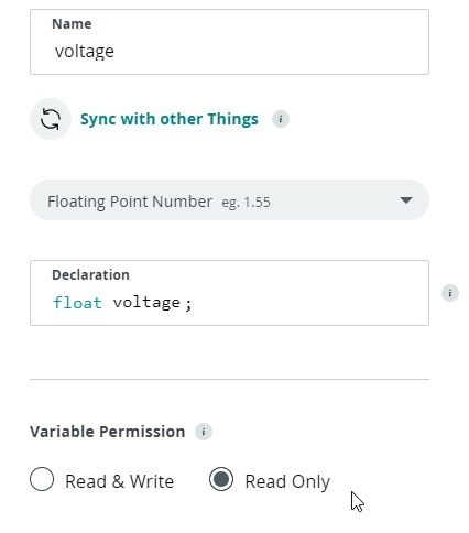
In the variable update policy we will select the on change and then click on the add variable.
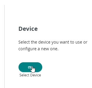
Now both the variables are created and we will add the device with the help of which we are going to monitor the system. Click on the device
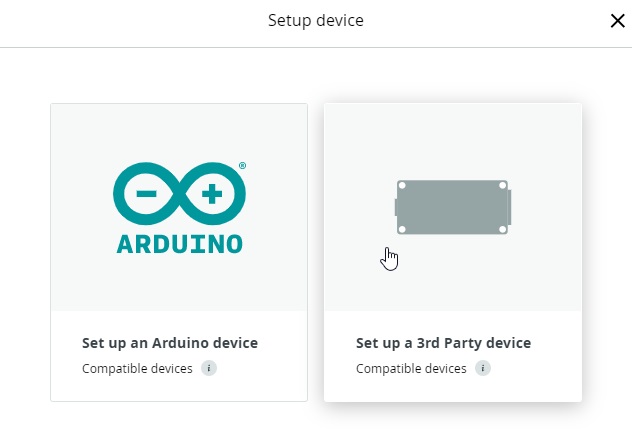
Now a dialog box will open and select a third party device
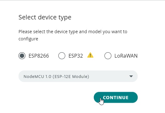
Now we will choose which type of the microcontroller board we are going to use, in our case we are using Nodemcu ESP8266 so, we will select the ESP8266 and also select its model and click on the continue button.
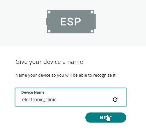
Then give the name to the device in our case we are using the name electronic clinic and click on the next button.
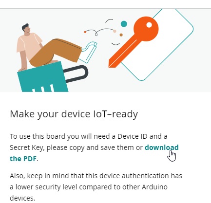
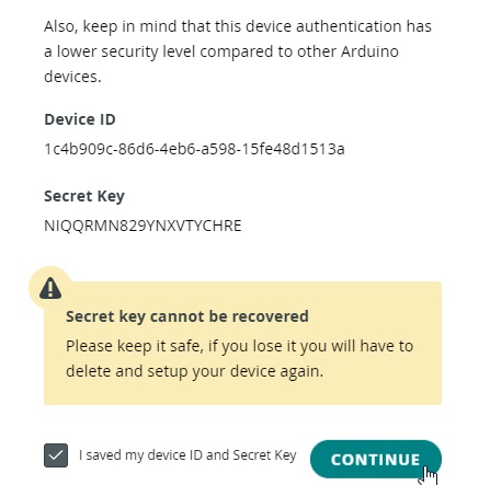
Now download the pdf file which consists of the security key and device id which will be used in configuring the network.
After downloading the id click on the I save my device id and security key and click on the continue button.
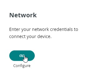
After clicking on the continue , the device is successfully added. Now after that we will click on the configure the network
After clicking the configure button a dialog box will appear in which we will enter the SSID means the router name, password, and the security key which we have copied during adding the device.

Now after entering the required values we will click on the save button.
Then we will click on the dashboard to design the application.
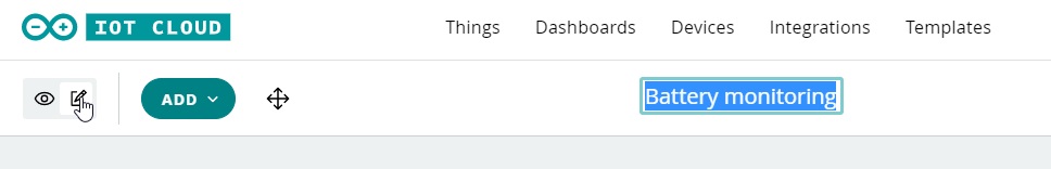
When we click on the dashboard a new window will open in which we will click on the edit button and now give a name to the project.
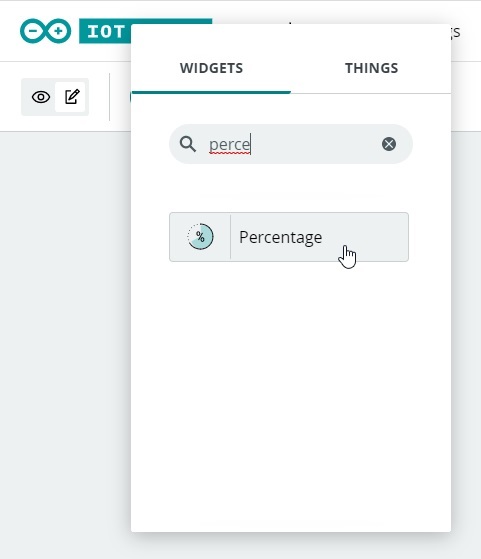
Then we will add the widget for the application by clicking on the add and we will select the percentage
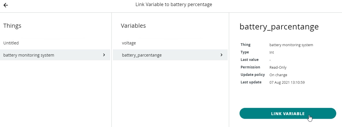
Then we will select the variable for it in our case we are using variable battery percentage which is int type select the battery percentage and click on the link variable.
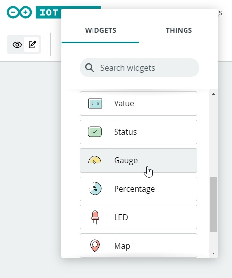
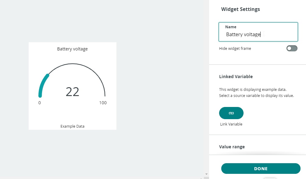
Now we will add gauge for the battery voltage by clicking on the add button
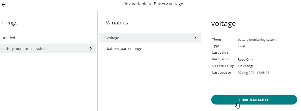
Then give a name to the gauge which is battery voltage and click on the link variable
When we click on the link variable we will select the variable which is voltage and click on the link variable.
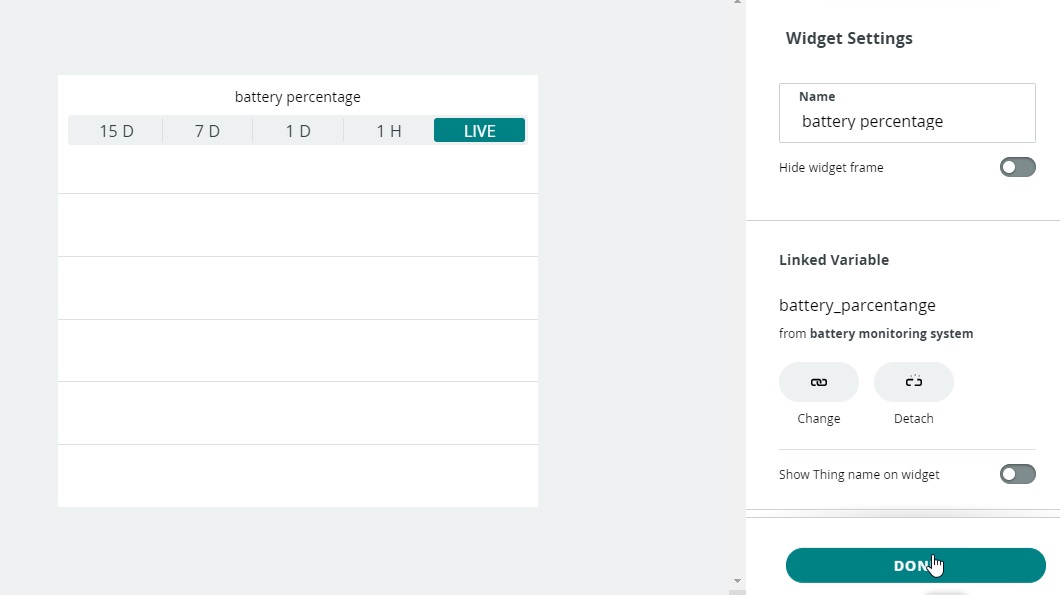
Then we will add the live chart for both the voltage and percentage now again click on the add button and select the chart. Now give a name battery percentage and linked it with the battery percentage variable and click on the done button.
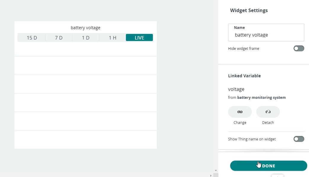
Similarly, we will again insert chart for the battery voltage and linked it with the variable voltage and click on the done button.
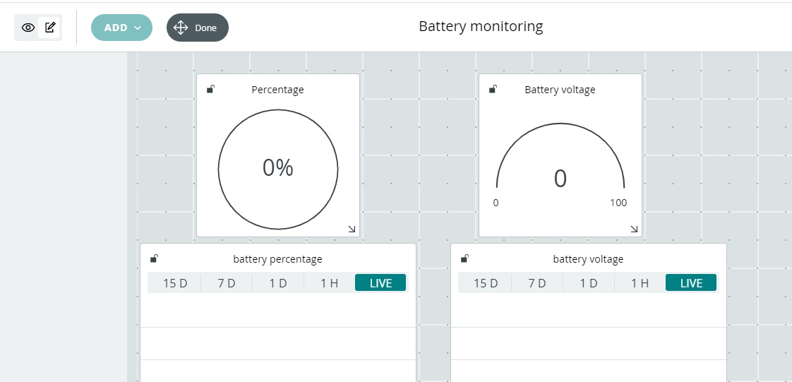
Now the application design is completed and it will look like
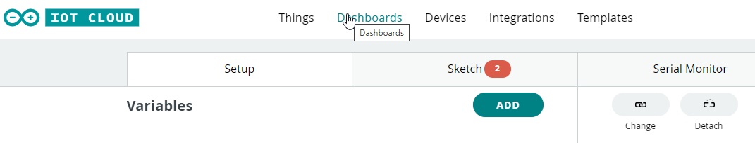
After that we will write the code by clicking on the sketch button
When we will click on the sketch button the code will appear, we will write the following code
Complete code:
|
1 2 3 4 5 6 7 8 9 10 11 12 13 14 15 16 17 18 19 20 21 22 23 24 25 26 27 28 29 30 31 32 33 34 35 36 37 38 39 40 41 42 43 44 45 46 47 48 49 50 51 52 53 54 55 56 57 58 59 60 61 62 63 64 65 66 67 68 69 70 71 72 |
/* Sketch generated by the ArduinoIoT Cloud Thing "battery monitoring system" https://create.arduino.cc/cloud/things/e5488df6-41ca-47da-acfe-d6c733bd4f8e ArduinoIoT Cloud Variables description The following variables are automatically generated and updated when changes are made to the Thing float voltage; int bat_percentage; Variables which are marked as READ/WRITE in the Cloud Thing will also have functions which are called when their values are changed from the Dashboard. These functions are generated with the Thing and added at the end of this sketch. */ #include "thingProperties.h" Int analogInPin = A0; // Analog input pin int sensorValue; float calibration = 0.36; // Check Battery voltage using multimeter & add/subtract the value void setup() { // Initialize serial and wait for port to open: Serial.begin(9600); // This delay gives the chance to wait for a Serial Monitor without blocking if none is found delay(1500); // Defined in thingProperties.h initProperties(); // Connect to ArduinoIoT Cloud ArduinoCloud.begin(ArduinoIoTPreferredConnection); /* The following function allows you to obtain more information related to the state of network and IoT Cloud connection and errors the higher number the more granular information you’ll get. The default is 0 (only errors). Maximum is 4 */ setDebugMessageLevel(2); ArduinoCloud.printDebugInfo(); } void loop() { ArduinoCloud.update(); ArduinoCloud.update(); sensorValue = analogRead(analogInPin); voltage = (((sensorValue * 3.3) / 1024) * 2 + calibration); //multiply by two as voltage divider network is 100K & 100K Resistor bat_percentage = mapfloat(voltage, 2.8, 4.2, 0, 100); //2.8V as Battery Cut off Voltage & 4.2V as Maximum Voltage if (bat_percentage>= 100) { bat_percentage = 100; } if (bat_percentage<= 0) { bat_percentage = 1; } Serial.print("Analog Value = "); Serial.print(sensorValue); Serial.print("\t Output Voltage = "); Serial.print(voltage); Serial.print("\t Battery Percentage = "); Serial.println(bat_percentage); delay(1000); } float mapfloat(float x, float in_min, float in_max, float out_min, float out_max) { return (x - in_min) * (out_max - out_min) / (in_max - in_min) + out_min; } |
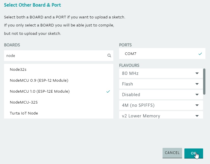
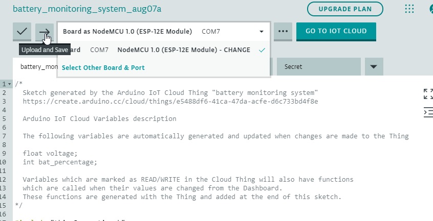
Now in order to upload the code we will first install the ArduinoCreateAgent which is necessary for uploading the code and then we will select the port and board.
After selecting the board and port we will upload the code
After uploading the code successfully
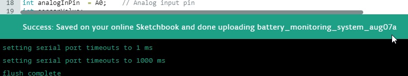
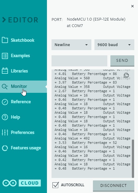
Then we will click on the serial monitor on which the battery voltage and percentage will be displayed.
Discover more from Electronic Clinic
Subscribe to get the latest posts sent to your email.