IOT Notice Board using Nodemcu ESP8266 & 8×8 LED Matrix
Last Updated on September 20, 2024 by Engr. Shahzada Fahad
Table of Contents
IoT Notice Board:
IOT Notice Board using Nodemcu ESP8266 & 8×8 LED Matrix- In this tutorial, you will learn how to make an IOT “Internet of Things” based Notice Board using Nodemcu ESP8266 Wifi Module, Max7219 8×8 LED Matrix modules, and Blynk application. The scrolling text message on the 8×8 LED Matrix can be updated at any time from anywhere around the world using the Blynk application. The scrolling speed of the text message can be controlled using a variable resistor or a Potentiometer. This is version 3 of the 8×8 scrolling message which is entirely based on my previous two tutorials.
Version1 is based on the computer-controlled scrolling text, while version2 is based on the Bluetooth controlled 8×8 LED Matrix Scrolling text display system. So, I highly recommend first read my previous two tutorials and then you can resume from here.
Without any further delay, let’s get started!!!
Amazon Product links:
MAX7219 8X8 LED Matrix module:
*Please Note: These are affiliate links. I may make a commission if you buy the components through these links. I would appreciate your support in this way!
8×8 Dot LED Matrix Module:

An LED matrix or LED display is a large, low-resolution form of dot-matrix display, useful both for industrial and commercial information displays as well as for hobbyist human-machine interfaces. It consists of a 2-D diode matrix with their cathodes joined in rows and their anodes joined in columns (or vice versa). By controlling the flow of electricity through each row and column pair it is possible to control each LED individually. By multiplexing, scanning across rows, quickly flashing the LEDs on and off, it is possible to create characters or pictures to display information to the user.
In this project, we are going to make a smart notice board, which can be controlled using wifi “internet”. The scrolling text can be updated using the Blynk application.
Max7219 8×8 LED Matrix Module:

This is the 8×8 dot LED Matrix module based on the MAX7219 chip. This module has a total of 10 pins. 5 pins on the input side and 5 pins on the output side. The pins on the input side are clearly labeled as CLK, CS, DIN, GND, and VCC. The pins on the output side are labeled in the same way except the middle pin which is labeled as the DOUT. So, these output pins are connected with the input pins of the other 8×8 dot Matrix LED module. So this way you can connect multiple 8×8 LED display modules which I will explain in the circuit diagram.
The module operating voltage is 5 Volts.
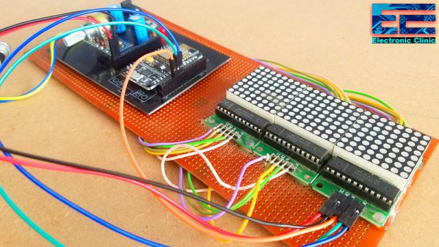
IoT Notice Board Circuit Diagram:

This is the complete circuit diagram of the IoT based Notice Board. As you can see the circuit diagram is very simple. The 8×8 LED matrix display modules are connected in the cascaded form. The output clock pin of the first 8×8 LED module is connected with the input clock pin of the second 8×8 LED display module. similarly, the output CS pin of the first 8×8 LED module is connected with the input CS pin of the second 8×8 LED module, the DOUT pin is connected with the Din pin of the 2nd 8×8 LED module and similarly, the GND and VCC pins of the first 8×8 LED module are connected with the GND and VCC of the second 8×8 LED module. The same connections are done for the third 8×8 Matrix LED display module. You can increase and decrease the number of 8×8 Matrix LED modules as per your requirement.
The Clock pin, CS pin, and DIN pins of the first 8×8 Matrix LED module are connected with the Nodemcu ESP8266 digital pins D6, D7, and D8. While the GND and VCC pins are connected with the 5 Volts regulated power supply based on the LM7805 voltage regulator. This power supply is used to power up the Nodemcu Module and all the 8×8 Matrix LED display modules. J1 is the female power jack and this is where we connect an adaptor, a 12 volts battery or a Solar Panel. Just by adding the solar panel you can turn this project into a solar-powered IoT Notice Board.
Finally, a variable resistor or Potentiometer R2 is connected with the Analog pin A0 of the Nodemcu Module. This variable resistor is used for controlling the scrolling speed of the text.
About the Nodemcu ESP8266 Power Supply PCB board and Sponsor:
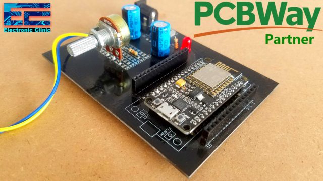
High quality & Only 24 Hours Build time
For the easy interfacing, I designed a PCB board for the Nodemcu ESP8266 Wifi Module. This PCB is sponsored and manufactured by the PCBway Company, which is one of the most experienced PCB and PCB assembly manufacturer. They create high-quality PCBs at reasonable prices. As you can see the quality is really great, the silkscreen is quite clear and the black solder mask looks amazing. I am 100% satisfied with their work. Now I can easily interface the Nodemcu ESP8266 Wifi module with the Arduino and other electronic devices.
Download Gerber files
Download link of the Nodemcu library for Cadsoft eagle
IoT Notice Board 8×8 LED Matrix Interfacing with Nodemcu ESP8266:
All the connections are done as per the circuit diagram already explained. Now let’s have a look at the Nodemcu ESP8266 Wifi Module programming.
IoT Notice Board Programming using Arduino IDE:
|
1 2 3 4 5 6 7 8 9 10 11 12 13 14 15 16 17 18 19 20 21 22 23 24 25 26 27 28 29 30 31 32 33 34 35 36 37 38 39 40 41 42 43 44 45 46 47 48 49 50 51 52 53 54 55 56 57 58 59 60 61 62 63 64 65 66 67 68 69 70 71 72 73 74 75 76 77 78 79 80 81 82 83 84 85 86 87 88 89 90 91 92 93 94 95 96 97 98 99 100 101 102 103 104 105 106 107 108 109 110 111 112 113 114 115 116 117 118 119 120 121 122 123 124 125 126 127 128 129 130 131 132 133 134 135 136 137 138 139 140 141 142 143 144 145 146 147 148 149 150 151 152 153 154 155 156 157 158 159 160 161 162 163 164 165 166 167 168 169 170 171 172 173 174 175 176 177 178 179 180 181 182 183 184 185 186 187 188 189 190 191 192 193 194 195 196 197 198 199 200 201 202 203 204 205 206 207 208 209 210 211 212 213 214 215 216 217 218 219 220 221 222 223 224 225 226 227 228 229 |
#define BLYNK_PRINT Serial #include <ESP8266WiFi.h> #include <BlynkSimpleEsp8266.h> //#include <BlynkSimpleEsp32.h> #include <SimpleTimer.h> #include <MaxMatrix.h> #include <avr/pgmspace.h> char auth[] = "0ErCPUEB2nN-s8j-vCMMAB8PyEwRWl8Q"; // Your WiFi credentials. // Set password to "" for open networks. char ssid[] = "AndroidAP7DF8"; char pass[] = "electroniclinic"; // Attach virtual serial terminal to Virtual Pin V1 WidgetTerminal terminal(V4); SimpleTimer timer; SimpleTimer timer2; String mymessage; void myTimerEvent() { // You can send any value at any time. // Please don't send more that 10 values per second. Blynk.virtualWrite(V1, millis() / 1000); } PROGMEM const unsigned char CH[] = { 3, 8, B00000000, B00000000, B00000000, B00000000, B00000000, // space 1, 8, B01011111, B00000000, B00000000, B00000000, B00000000, // ! 3, 8, B00000011, B00000000, B00000011, B00000000, B00000000, // " 5, 8, B00010100, B00111110, B00010100, B00111110, B00010100, // # 4, 8, B00100100, B01101010, B00101011, B00010010, B00000000, // $ 5, 8, B01100011, B00010011, B00001000, B01100100, B01100011, // % 5, 8, B00110110, B01001001, B01010110, B00100000, B01010000, // & 1, 8, B00000011, B00000000, B00000000, B00000000, B00000000, // ' 3, 8, B00011100, B00100010, B01000001, B00000000, B00000000, // ( 3, 8, B01000001, B00100010, B00011100, B00000000, B00000000, // ) 5, 8, B00101000, B00011000, B00001110, B00011000, B00101000, // * 5, 8, B00001000, B00001000, B00111110, B00001000, B00001000, // + 2, 8, B10110000, B01110000, B00000000, B00000000, B00000000, // , 4, 8, B00001000, B00001000, B00001000, B00001000, B00000000, // - 2, 8, B01100000, B01100000, B00000000, B00000000, B00000000, // . 4, 8, B01100000, B00011000, B00000110, B00000001, B00000000, // / 4, 8, B00111110, B01000001, B01000001, B00111110, B00000000, // 0 3, 8, B01000010, B01111111, B01000000, B00000000, B00000000, // 1 4, 8, B01100010, B01010001, B01001001, B01000110, B00000000, // 2 4, 8, B00100010, B01000001, B01001001, B00110110, B00000000, // 3 4, 8, B00011000, B00010100, B00010010, B01111111, B00000000, // 4 4, 8, B00100111, B01000101, B01000101, B00111001, B00000000, // 5 4, 8, B00111110, B01001001, B01001001, B00110000, B00000000, // 6 4, 8, B01100001, B00010001, B00001001, B00000111, B00000000, // 7 4, 8, B00110110, B01001001, B01001001, B00110110, B00000000, // 8 4, 8, B00000110, B01001001, B01001001, B00111110, B00000000, // 9 2, 8, B01010000, B00000000, B00000000, B00000000, B00000000, // : 2, 8, B10000000, B01010000, B00000000, B00000000, B00000000, // ; 3, 8, B00010000, B00101000, B01000100, B00000000, B00000000, // < 3, 8, B00010100, B00010100, B00010100, B00000000, B00000000, // = 3, 8, B01000100, B00101000, B00010000, B00000000, B00000000, // > 4, 8, B00000010, B01011001, B00001001, B00000110, B00000000, // ? 5, 8, B00111110, B01001001, B01010101, B01011101, B00001110, // @ 4, 8, B01111110, B00010001, B00010001, B01111110, B00000000, // A 4, 8, B01111111, B01001001, B01001001, B00110110, B00000000, // B 4, 8, B00111110, B01000001, B01000001, B00100010, B00000000, // C 4, 8, B01111111, B01000001, B01000001, B00111110, B00000000, // D 4, 8, B01111111, B01001001, B01001001, B01000001, B00000000, // E 4, 8, B01111111, B00001001, B00001001, B00000001, B00000000, // F 4, 8, B00111110, B01000001, B01001001, B01111010, B00000000, // G 4, 8, B01111111, B00001000, B00001000, B01111111, B00000000, // H 3, 8, B01000001, B01111111, B01000001, B00000000, B00000000, // I 4, 8, B00110000, B01000000, B01000001, B00111111, B00000000, // J 4, 8, B01111111, B00001000, B00010100, B01100011, B00000000, // K 4, 8, B01111111, B01000000, B01000000, B01000000, B00000000, // L 5, 8, B01111111, B00000010, B00001100, B00000010, B01111111, // M 5, 8, B01111111, B00000100, B00001000, B00010000, B01111111, // N 4, 8, B00111110, B01000001, B01000001, B00111110, B00000000, // O 4, 8, B01111111, B00001001, B00001001, B00000110, B00000000, // P 4, 8, B00111110, B01000001, B01000001, B10111110, B00000000, // Q 4, 8, B01111111, B00001001, B00001001, B01110110, B00000000, // R 4, 8, B01000110, B01001001, B01001001, B00110010, B00000000, // S 5, 8, B00000001, B00000001, B01111111, B00000001, B00000001, // T 4, 8, B00111111, B01000000, B01000000, B00111111, B00000000, // U 5, 8, B00001111, B00110000, B01000000, B00110000, B00001111, // V 5, 8, B00111111, B01000000, B00111000, B01000000, B00111111, // W 5, 8, B01100011, B00010100, B00001000, B00010100, B01100011, // X 5, 8, B00000111, B00001000, B01110000, B00001000, B00000111, // Y 4, 8, B01100001, B01010001, B01001001, B01000111, B00000000, // Z 2, 8, B01111111, B01000001, B00000000, B00000000, B00000000, // [ 4, 8, B00000001, B00000110, B00011000, B01100000, B00000000, // \ backslash 2, 8, B01000001, B01111111, B00000000, B00000000, B00000000, // ] 3, 8, B00000010, B00000001, B00000010, B00000000, B00000000, // hat 4, 8, B01000000, B01000000, B01000000, B01000000, B00000000, // _ 2, 8, B00000001, B00000010, B00000000, B00000000, B00000000, // ` 4, 8, B00100000, B01010100, B01010100, B01111000, B00000000, // a 4, 8, B01111111, B01000100, B01000100, B00111000, B00000000, // b 4, 8, B00111000, B01000100, B01000100, B00101000, B00000000, // c 4, 8, B00111000, B01000100, B01000100, B01111111, B00000000, // d 4, 8, B00111000, B01010100, B01010100, B00011000, B00000000, // e 3, 8, B00000100, B01111110, B00000101, B00000000, B00000000, // f 4, 8, B10011000, B10100100, B10100100, B01111000, B00000000, // g 4, 8, B01111111, B00000100, B00000100, B01111000, B00000000, // h 3, 8, B01000100, B01111101, B01000000, B00000000, B00000000, // i 4, 8, B01000000, B10000000, B10000100, B01111101, B00000000, // j 4, 8, B01111111, B00010000, B00101000, B01000100, B00000000, // k 3, 8, B01000001, B01111111, B01000000, B00000000, B00000000, // l 5, 8, B01111100, B00000100, B01111100, B00000100, B01111000, // m 4, 8, B01111100, B00000100, B00000100, B01111000, B00000000, // n 4, 8, B00111000, B01000100, B01000100, B00111000, B00000000, // o 4, 8, B11111100, B00100100, B00100100, B00011000, B00000000, // p 4, 8, B00011000, B00100100, B00100100, B11111100, B00000000, // q 4, 8, B01111100, B00001000, B00000100, B00000100, B00000000, // r 4, 8, B01001000, B01010100, B01010100, B00100100, B00000000, // s 3, 8, B00000100, B00111111, B01000100, B00000000, B00000000, // t 4, 8, B00111100, B01000000, B01000000, B01111100, B00000000, // u 5, 8, B00011100, B00100000, B01000000, B00100000, B00011100, // v 5, 8, B00111100, B01000000, B00111100, B01000000, B00111100, // w 5, 8, B01000100, B00101000, B00010000, B00101000, B01000100, // x 4, 8, B10011100, B10100000, B10100000, B01111100, B00000000, // y 3, 8, B01100100, B01010100, B01001100, B00000000, B00000000, // z 3, 8, B00001000, B00110110, B01000001, B00000000, B00000000, // { 1, 8, B01111111, B00000000, B00000000, B00000000, B00000000, // | 3, 8, B01000001, B00110110, B00001000, B00000000, B00000000, // } 4, 8, B00001000, B00000100, B00001000, B00000100, B00000000, // ~ }; int vr = A0; // variable resistor for controlling speed int data = D8; // 8, DIN pin of MAX7219 module int load = D7; // 9, CS pin of MAX7219 module int clock = D6; // 10, CLK pin of MAX7219 module int maxInUse = 3; //change this variable to set how many MAX7219's you'll use MaxMatrix m(data, load, clock, maxInUse); // define module byte buffer[10]; char c; String str; char cstr[100]; unsigned int mlength; // message length int textspeed = 100; // default speed void setup() { // Debug console Serial.begin(9600); Blynk.begin(auth, ssid, pass); timer.setInterval(1000L,message); timer2.setInterval(1000L,speedcontrol); m.init(); // module initialize m.setIntensity(15); // dot matix intensity 0-15 pinMode(vr, INPUT); } void loop() { Blynk.run(); timer.run(); timer2.run(); } BLYNK_WRITE(V4) { // if you type "Marco" into Terminal Widget - it will respond: "Polo:" mymessage = param.asStr(); } void message() { m.shiftLeft(false, true); mlength = mymessage.length(); // find the number of characters in a message. str = mymessage; str.toCharArray(cstr,100); printStringWithShift(cstr, textspeed); } void speedcontrol() { int vrdata = analogRead(vr); textspeed = map(vrdata,0,1023,0,200); } void printCharWithShift(char c, int shift_speed){ if (c < 32) return; c -= 32; memcpy_P(buffer, CH + 7*c, 7); m.writeSprite(maxInUse*8, 0, buffer); m.setColumn(maxInUse*8 + buffer[0], 0); for (int i=0; i<buffer[0]+1; i++) { delay(shift_speed); m.shiftLeft(false, false); } } void printStringWithShift(char* s, int shift_speed){ while (*s != 0){ printCharWithShift(*s, shift_speed); s++; } } void printString(char* s) { int col = 0; while (*s != 0) { if (*s < 32) continue; char c = *s - 32; memcpy_P(buffer, CH + 7*c, 7); m.writeSprite(col, 0, buffer); m.setColumn(col + buffer[0], 0); col += buffer[0] + 1; s++; } } |
IOT Notice Board program explanation:
All the libraries used in this project can be downloaded by clicking on the download link given below.
Download Arduino Libraries:
This is almost the same program that I have already explained in my previous 8×8 LED Matrix-based projects, this time I added the libraries for the esp8266 and Blynk. Added the authentication token which is generated the time we create a new project in Blynk. I added the name of my wifi router and password.
I defined pins for the Variable resistor, DIN, CS, and Clock pins.
String str;
char cstr[100];
unsigned int mlength; // message length
int textspeed = 100; // default speed
Finally, I defined some variables of the typed string and char, and integer, which later will be used for converting a string message into an array of characters and controlling the scrolling speed of the text message.
The rest of the programming is exactly the same as explained in my previous tutorials. So that’s all about the IoT based Notice Board programming. Now, let’s make the Blynk application.
Note: this old version of the Blynk app is no more functional. For the blynk mobile App setup and Blynk.cloud dashboard setup ready my article on the New Blynk V2.0. In this article I have explained how to migrate your projects from Blynk 1.0 to the new Blynk V2.0. You can also watch the video.
Cell phone application for the IoT Notice Board, Blynk App:
So finally, we need a cell phone application that we can use to send messages to the 8×8 Matrix LED. For this Blynk is the best choice, it’s free and easy to use.
- First of all, open the blynk application.
- Click on the create a new project, enter the project name, select Nodemcu, and make sure you select the wifi.
- Click on the create button, an authentication token will be sent on your email id. This authentication token will be used in the programming, which you can see in the programming given above.
- Now, click anywhere on the screen and search for the terminal widget and add it.
- Click on the terminal widget, click on the pin and select virtual pin V4.
Our application is ready. For the step by step explanation, watch the video given below.
Watch Video Tutorial:

Discover more from Electronic Clinic
Subscribe to get the latest posts sent to your email.

Fahad sb A.O.A
Sir i m electronic engineer and my hobby is arduino projects but i have no experience in programming.i am working on net projects in which some are functinal..today i m using your electronic clinic web site and i feel happy bcz your projects are functional..you are one great person who is showing free projects…if i need your help then can you help me ?
Thanks
Imran