IoT Smoke Detector using MQ135 Gas Sensor & Nodemcu ESP8266
Last Updated on September 21, 2024 by Engr. Shahzada Fahad
Table of Contents
IoT Smoke Detector:
IoT Smoke Detector- In this tutorial, you will learn how to make an IoT based Smoke Detector system using Nodemcu ESP8266 Wifi module, MQ135 Gas Sensor and Blynk application. The sensor value can be monitored in real time from anywhere around the world. When the sensor value crosses a certain pre-defined value a notification message is sent to the concerned person.
The PCB board used in this project is sponsored by the PCBway Company which is one of the top leading companies throughout the world. The PCB board Gerber files can be downloaded from the PCBway official website.
In this episode, I will cover
- MQ135 Sensor Pinout explanation.
- Complete circuit diagram explanation
- PCB board layout explanation.
- Nodemcu ESP8266 Wifi Module Programming
- Testing
Without any further delay, let’s get started!!!
Amazon Links:
Please Note: these are affiliate links. I may make a commission if you buy the components through these links. I would appreciate your support in this way!
MQ135 Gas Sensor:
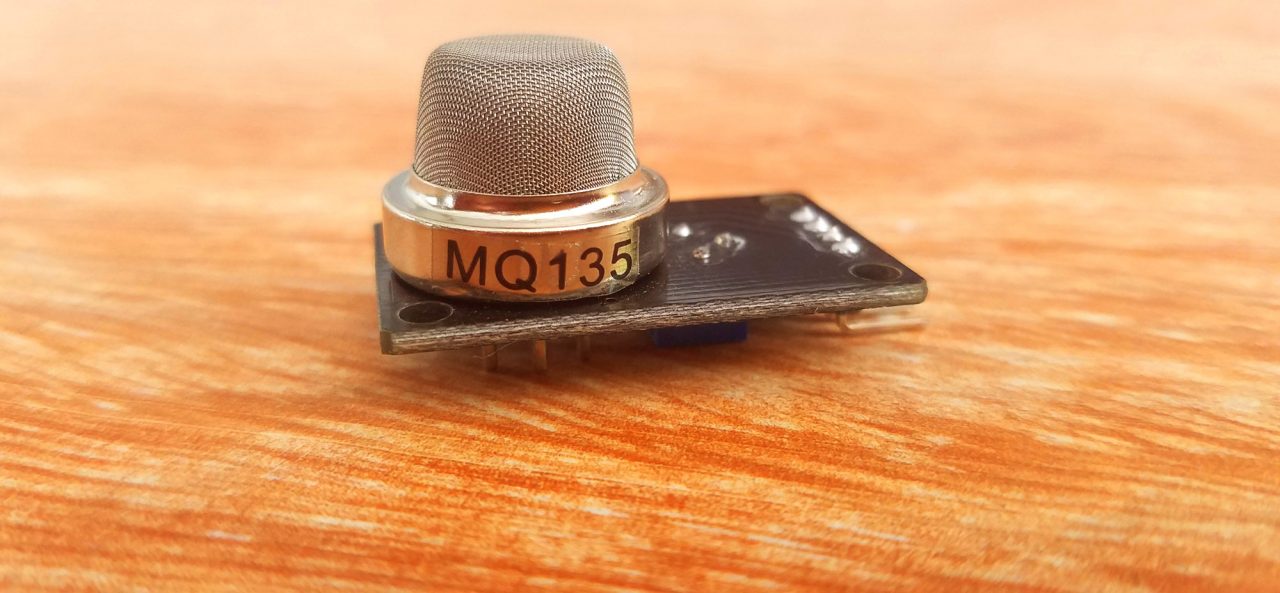
This is the MQ135 Gas Sensor which is quite sensitive to Benzene, Alcohol, and Smoke. The output voltage of this sensor increases as the concentration of the gases increases. This sensor is famous for the fast response and recovery. The sensitivity can be adjusted very easily using the blue color variable resistor.
Specifications:
To power up this sensor you need 2.5V to 5 volts, which is perfect. You can use this sensor with Arduino and Nodemcu ESP8266 Wifi module. This sensor is most commonly used as the Air Quality monitor.
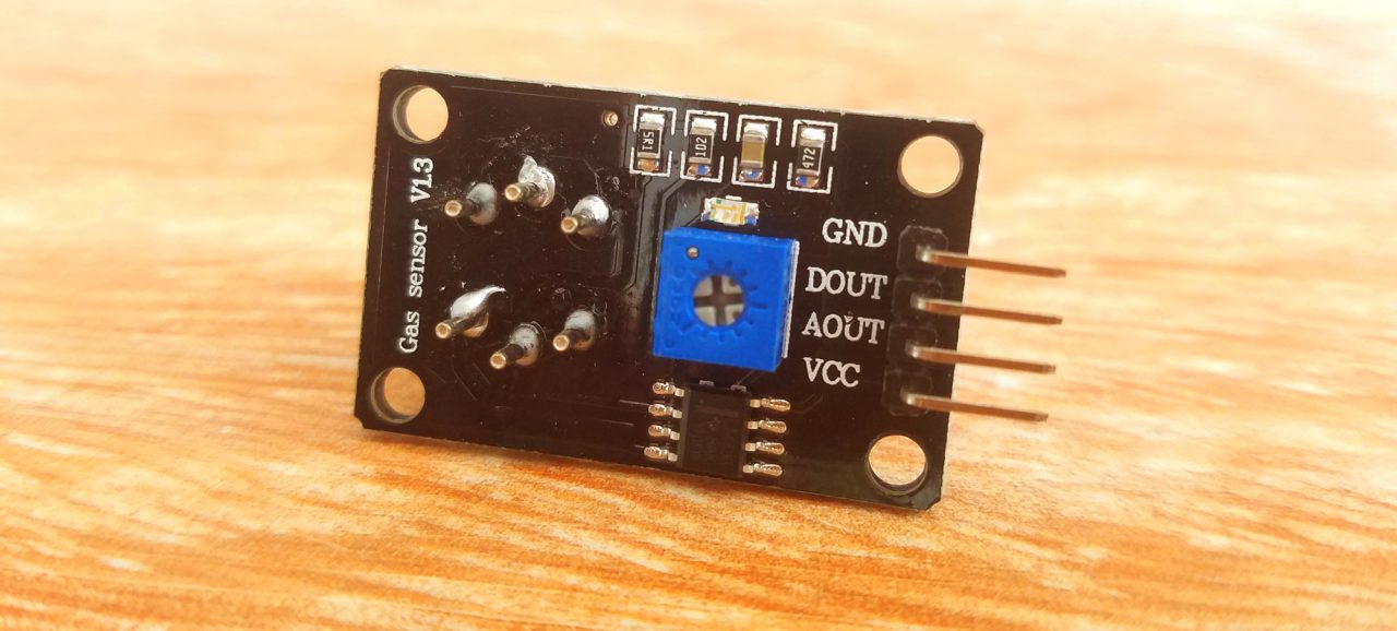
MQ135 Pinout:
As you can see, the MQ135 Gas Sensor has a total of 4 male headers, which are clearly labeled as GND, DOUT which is the digital output, AOUT which is the analog output, and VCC.
IoT Smoke Detector Circuit Diagram:

This is the complete circuit diagram of the IoT based Smoke detector system. As you can see the circuit diagram is very simple. This project can be divided into three sections, the power supply, the Nodemcu ESP8266 wifi Module, and the MQ135 Gas Sensor. Let’s first start with the Power Supply. The Power Supply is based on the famous LM7805 voltage regulator. J1 is the female power jack and this is where we connect a 12v adaptor, battery or a solar panel. Two 470uf capacitors are connected at the input and output sides of the voltage regulator. A 330-ohm resistor is connected in series with a 2.5v led. This is a current limiting resistor. The output of the voltage regulator is connected with the Vin pin of the Nodemcu ESP8266 wifi module and the ground is connected with the ground. SV1 and SV2 are the female headers.
The ground of the MQ135 Gas Sensor is connected with the ground of the Nodemcu module, the AOUT pin is connected with the Analog pin A0 of the Nodemcu Module, and VCC is connected with the 3.3 volts pin of the Nodemcu ESP8266 Wifi Module.
IoT Smoke Detector PCB Board layout:
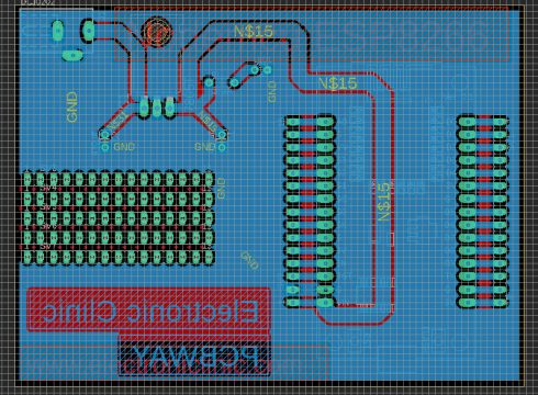
I have already explained the PCB designing, I will provide a link in the related projects section if in case you want to learn how to make your own PCB using the Cadsoft eagle PCB designing software. After I was done with the PCB designing, I generated the Gerber files and placed an online order on the PCBway official website.
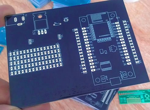
This is the PCB board which I received from the PCBway Company. As you can see the quality is really great and everything is as per the order. The silkscreen is quite clear, the Black color Soldermask looks amazing. I am 100% satisfied with their work. The Gerber files of this PCB can be downloaded from the PCBway website. The link is given below.
Download the Gerber files
Download the Eagle PCB board layout file: nodemcu esp8266 power supply pcb board
Soldering:
The soldering is explained in the video tutorial given at the end of this article.
MQ135 Gas Sensor Interfacing with Nodemcu ESP8266:
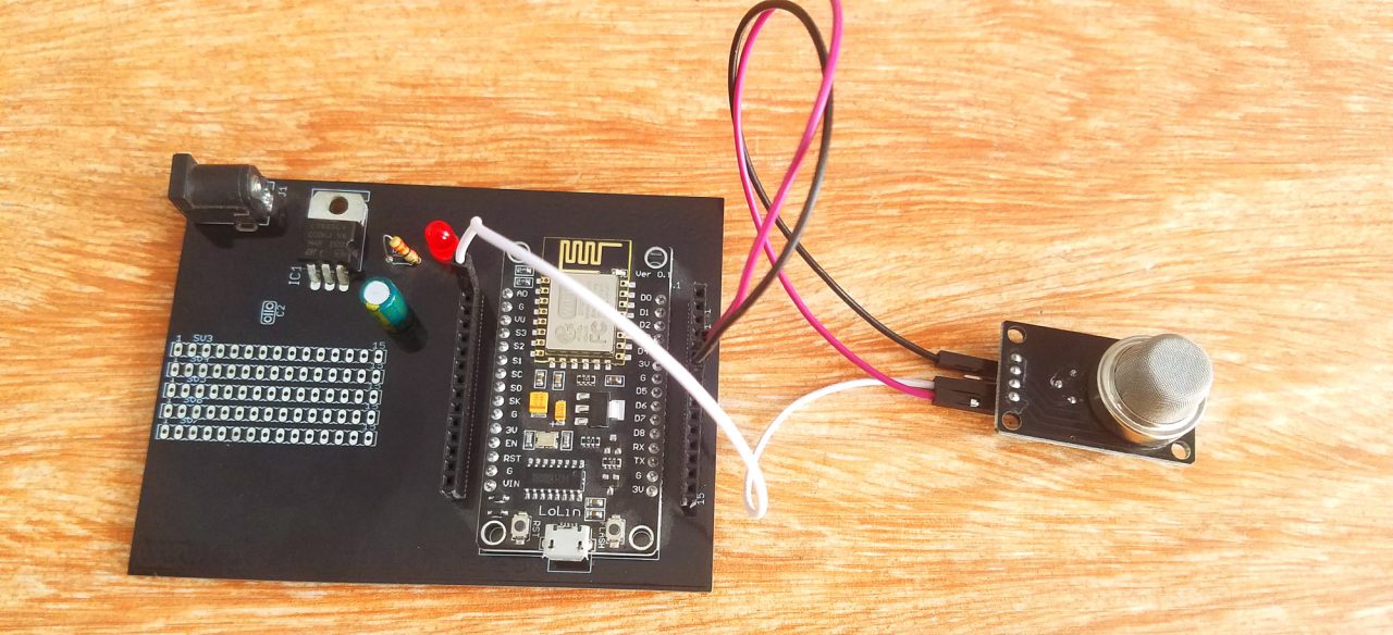
The VCC pin of the MQ135 Gas Sensor is connected with the Nodemcu Module 3.3 volts pin, the AOUT pin is connected with the A0 pin of the Nodemcu Module and the ground of the Gas Sensor is connected with the ground of the Nodemcu ESP8266 Wifi Module.
Note: this old version of the Blynk app is no more functional. For the blynk mobile App setup and Blynk.cloud dashboard setup ready my article on the New Blynk V2.0. In this article I have explained how to migrate your projects from Blynk 1.0 to the new Blynk V2.0. You can also watch the video.
Blynk application designing:
For the step by step explanation, you can watch the video tutorial given at the end of this article or you can follow the following steps.
- First of all, open the blynk application.
- Click on the new project and enter the project name.
- Click on the choose device and select Nodemcu.
- Make sure the connection type is set to WIFI.
- Finally, click on the create button, an authentication token will be sent on your email id, which later will be used in the Nodemcu programming.
- Click anywhere on the screen and search for the notification widget and add it.
- Again click on the screen and this time search for the Gauge and add it.
- Click on the gauge.
- Set the gauge name.
- Click on the PIN and select virtual pin V2.
- Change the font size.
- Click on PUSH and select 1 second.

That’s it. Our application is ready now let’s discuss the Nodemcu programming.
IoT Smoke Detector Nodemcu ESP8266 Programming:
|
1 2 3 4 5 6 7 8 9 10 11 12 13 14 15 16 17 18 19 20 21 22 23 24 25 26 27 28 29 30 31 32 33 34 35 36 37 38 39 40 41 42 |
/* ESP & Blynk */ #include <ESP8266WiFi.h> #include <BlynkSimpleEsp8266.h> #include <SimpleTimer.h> #define BLYNK_PRINT Serial // Comment this out to disable prints and save space char auth[] = "eYOJ9pkawJlSNzDLlOPUd7RkipGWHvqO"; /* WiFi credentials */ char ssid[] = "ZONG MBB-E8231-6E63"; char pass[] = "electroniclinic"; SimpleTimer timer; int mq135 = A0; // smoke sensor is connected with the analog pin A0 int data = 0; void setup() { Serial.begin(115200); Blynk.begin(auth, ssid, pass); timer.setInterval(1000L, getSendData); } void loop() { timer.run(); // Initiates SimpleTimer Blynk.run(); } /*************************************************** * Send Sensor data to Blynk **************************************************/ void getSendData() { data = analogRead(mq135); Blynk.virtualWrite(V2, data); //virtual pin V3 if (data > 600 ) { Blynk.notify("Smoke Detected!!!"); } } |
IoT Smoke Detector Program explanation:
Before you start the programming, first of all, make sure that you download all the necessary libraries. Click on the link below to download the libraries.
Download Libraries
/* ESP & Blynk */
#include <ESP8266WiFi.h>
#include <BlynkSimpleEsp8266.h>
#include <SimpleTimer.h>
#define BLYNK_PRINT Serial // Comment this out to disable prints and save space
char auth[] = “eYOJ9pkawJlSNzDLlOPUd7RkipGWHvqO”;
This is the authentication number which was sent via email, I simply copied and paste it over here.
/* WiFi credentials */
char ssid[] = “ZONG MBB-E8231-6E63”;
This is the name of the wifi router.
char pass[] = “electroniclinic”;
This is the Password.
SimpleTimer timer;
int mq135 = A0; // smoke sensor is connected with the analog pin A0
The MQ135 Gas Sensor is connected with the Analog pin A0 of the Nodemcu Module.
int data = 0;
data is a variable of the type integer and this will be used for storing the values coming from the MQ135 Gas Sensor.
void setup()
{
Serial.begin(115200);
Blynk.begin(auth, ssid, pass);
timer.setInterval(1000L, getSendData);
}
In the void setup function we set the baud rate which is 115200, this is only used for the debugging purposes. getSendData is a user defined function and is called every 1 second.
void loop()
{
timer.run(); // Initiates SimpleTimer
Blynk.run();
}
In the void loop function we have only two functions, timer.run and blynk.run.
/***************************************************
* Send Sensor data to Blynk
**************************************************/
void getSendData()
{
data = analogRead(mq135);
Blynk.virtualWrite(V2, data); //virtual pin V3
if (data > 600 )
{
Blynk.notify(“Smoke Detected!!!”);
}
}
As I said earlier the getSendData is a user defined function. This function has no return type and does not take any argument as the input. This function is used to read the MQ135 Gas Sensor and send the value to the blynk application where this value is displayed on the gauge.
if (data > 600 )
{
Blynk.notify(“Smoke Detected!!!”);
}
This condition is used to send a notification message, if the Sensor value increases above 600. So that’s all about the Nodemcu programming.
For the practical demonstration watch video tutorial given below.
Watch Video Tutorial:
How to make a Schematic and PCB:
Discover more from Electronic Clinic
Subscribe to get the latest posts sent to your email.

Hi! According to the datasheet on MQ135 it need 5V+/1 0,1!
Where did you find the 2,5…5V?
At the moment, this is the easiest way to connect MQ135 to esp, but i doubt the display is correct .