Linear Actuator Long Range Wireless Control System using Arduino, NRF24L01, & Bluetooth
Table of Contents
Linear Actuator Wireless Control, Description:
With a linear actuator, you can make an automatic door opening and closing system, you can make a solar tracker, an automatic system for your dish antenna, TV stand, etc. There are thousands of projects in which you can use an Electric Linear Actuator.
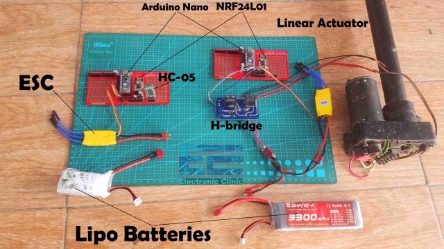
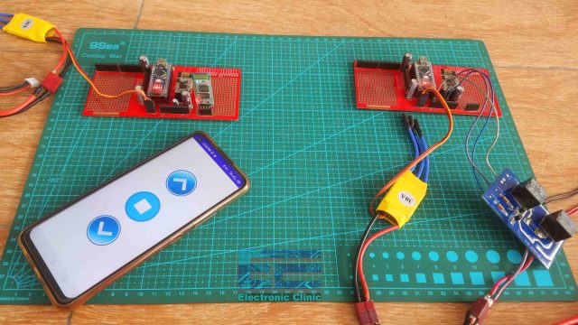
In this tutorial, you will learn how to make a long range wireless remote control system for an electric linear actuator using Arduino, NRF24L01 RF Transceiver Module, HC-05 Bluetooth module, and an Android application designed in Android studio. The control commands are sent from the Android app to the Arduino Nano wirelessly using Bluetooth. Arduino processes the command and then sends it to the Arduino board on the Receiver side using the NRF24L01 RF transceiver module. The Arduino then controls the linear actuator. Our designed Android App can send three commands which are used to control the forward movement of the shaft, reverse movement of the shaft, and to stop the Linear Actuator. For the practical demonstration watch the video tutorial given at the end of this article.
Isn’t it amazing? You don’t need any extra hardware to keep with you all the time, you can just take out your cell phone and start controlling your Linear actuator which is installed within 1-kilometer range if you are using PA + LNA version of the NRF24L01 modules. Now, you have got the idea of what you are going to learn after reading this article.
Note: The yellow color ESCs are only used to provide 5 volts to the Arduino, you can use your laptop to power up the Arduino or you can use any other external 5v regulated power supply.
Without any further delay, let’s get started!!!
Amazon Links:
Arduino Nano USB-C Type (Recommended)
Other Tools and Components:
ESP32 WiFi + Bluetooth Module (Recommended)
Super Starter kit for Beginners
PCB small portable drill machines
*Please Note: These are affiliate links. I may make a commission if you buy the components through these links. I would appreciate your support in this way!
What is Linear Actuator and it’s working:
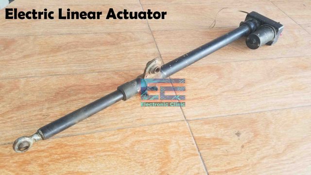
A Linear Actuator is an Actuator that creates motion in a straight line. We have both AC and DC types of Linear Actuators. The one you can see right now is the DC-type Linear Actuator. So, this is an electric Linear Actuator that converts DC electric Motor’s rotational motion into linear motion, which can be used for lifting, sliding, Dropping or tilting of machines or materials. Inside the Linear Actuator, the DC motor is provided with gears to reduce the speed and to increase the torque.
Working of Linear Actuator:
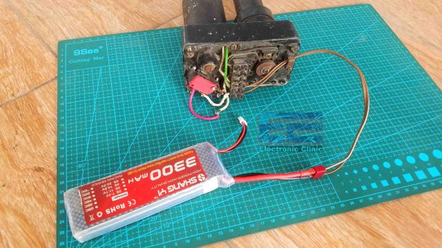
It has two wires and when connected with the desired voltage the shaft will start moving in the forward direction or in the reverse direction, let’s say it’s moving in the forward direction, now if you want to change the direction of movement all you need is to change the polarity and that’s it. Now, this is the simplest and manual way of controlling the Linear Actuator. For changing the polarity we will make our own H-bridge circuit, which I will explain later in this video.
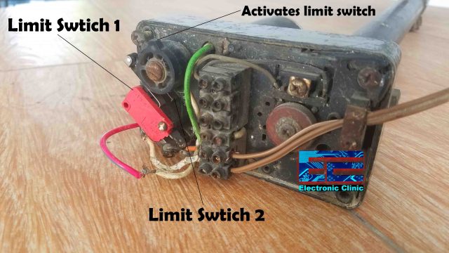
The Linear actuators are also provided with limit switches which define the maximum and minimum endpoints. Some Linear actuators are designed in a way that the endpoints can be adjusted as per the requirement, like the one you can see on the screen. You can unscrew this part “the part that activates the limit switch” and change the position to set the lower and upper, or minimum and maximum endpoints.
The main advantage of setting the endpoints is that, when you power up the Linear Actuator, you don’t need to be worried, the limit switches will automatically turn off the motor when any of the two limit switches is activated. So, when the lower limit switch is activated the motor will stop and will stay on this position until the polarity is changed, and then the shaft starts moving in the forward or upward direction. The shaft will keep moving until the upper limit switch is activated. This way the movement of the shaft can be precisely controlled between two points.
The type of electric Linear Actuator I am using needs 24V DC, but for demonstration purposes, I am using an 11.1V Lipo Battery, and this is why the shaft moves slowly. Now, let’s take a look at the transmitter and receiver circuit diagrams.
Transmitter Circuit Diagram:
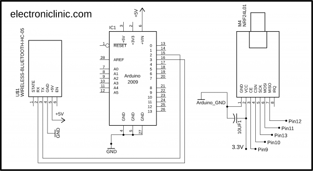
On the transmitter side, we have a Bluetooth module HC-05, Arduino Nano, and NRF24L01 transceiver module. The 5v and GND pins of the Bluetooth module are connected with the 5v and GND pins of the Arduino. The RX and TX pins of the Bluetooth module are connected with the Arduino pins 2 and 3.
A decoupling capacitor of 10uf is connected with the VCC and GND pins of the NRF24L01 module. The VCC and GND pins are connected with the Arduino’s 3.3V and GND pins. CE is connected with Pin9, CSN is connected with Pin10, SCK is connected with 13, MOSI is connected with Pin11, and the MISO pin is connected with Pin12 of the Arduino. Now, let’s take a look at the receiver side circuit diagram.
Receiver Circuit Diagram:
The NRF24L01 connection with the Arduino remains exactly the same. The circuit on the left side is basically an H-bridge circuit that is used to control the forward and reverse movement of the Linear Actuator. This H-bridge circuit changes the polarity of the voltage supplied to the motor. The two relays are controlled using Arduino pins 2 and 3. If you want to know in detail about the working of the H-bridge circuit then read my article on “Relay H-bridge Driver circuit and simulation with calculations”.
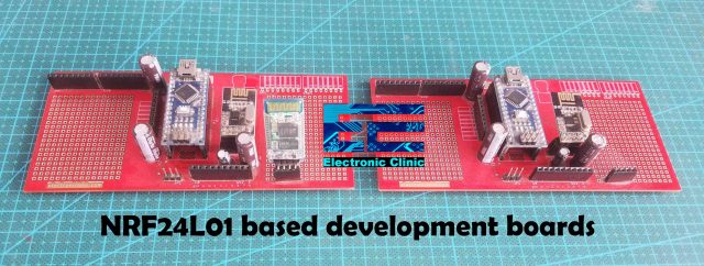
These are the development boards I designed for testing my NRF24L01 based projects, these are the same development boards I have been using in my previous projects.
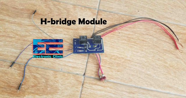
This is the H-bridge module designed as per the circuit diagram.
Download H-bridge Gerber Files:
Android App Designing:
You will need an android app to control this Linear Actuator. In my previous article, I have already explained how to design your own Bluetooth-supported Android App using Android studio. This tutorial will help you in designing cool android apps for your Arduino projects.
Transmitter Programming:
|
1 2 3 4 5 6 7 8 9 10 11 12 13 14 15 16 17 18 19 20 21 22 23 24 25 26 27 28 29 30 31 32 33 34 35 36 37 38 39 40 41 42 43 44 45 46 47 48 49 50 51 52 53 54 55 56 57 58 59 60 61 62 63 64 65 66 67 68 69 70 71 72 73 74 75 76 77 78 79 80 |
// Node01 #include <RF24.h> #include <RF24Network.h> #include <SPI.h> #include <Wire.h> #include <VirtualWire.h> #include <SoftwareSerial.h> #include <SimpleTimer.h> SoftwareSerial Blue(3, 2); int Bdata; SimpleTimer timer1; RF24 radio(9, 10); // nRF24L01 (CE,CSN) RF24Network network(radio); // Include the radio in the network const uint16_t this_node = 01; // Address of this node in Octal format const uint16_t node00 = 00; unsigned long data[6]; // number of sensors unsigned long data1; unsigned long data2; void setup() { Serial.begin(9600); Blue.begin(9600); SPI.begin(); radio.begin(); network.begin(90, this_node); //(channel, node address) radio.setDataRate(RF24_2MBPS); timer1.setInterval(50L, Sensor1Send); } void loop() { while(Blue.available()==0) { timer1.run(); network.update(); DataReceive(); } if(Blue.available()>0) { Bdata = Blue.parseInt(); } Serial.println(Bdata); } void Sensor1Send() // this funcion is controlled using a timer1 { data[0] = Bdata; RF24NetworkHeader header7(node00); bool ok = network.write(header7, &data, sizeof(data)); // Send the data } void DataReceive() { while ( network.available() ) { // Is there any incoming data? RF24NetworkHeader header; network.read(header, &data, sizeof(data)); // Read the incoming data if (header.from_node == 0) { // If data comes from Node 01 data1 = data[0]; Serial.println("Master Node00:"); Serial.println(data1); } if (header.from_node == 2) { // If data comes from Node 02 data2 = data[0]; } } } |
The transmitter and receiver side programming I have already explained in my previous tutorial based on the Wireless Sensor network, which I highly recommend you should read, because I have explained the most basics things, including how to create different nodes. For this project, I made a few changes.
I added the SoftwareSerial.h header file, which I used for creating another serial port on pins 3 and 2 of the Arduino Nano.
Inside the setup() function, I activated the Bluetooth module.
Inside the loop() function, I added code for the Bluetooth module. If no data is received from the Bluetooth module then simply run this block of code and if the data is received from the Bluetooth module then store the received value in variable Bdata and finally, this value is stored in the array data at the location 0 and is sent to the node00.
Receiver Programming:
|
1 2 3 4 5 6 7 8 9 10 11 12 13 14 15 16 17 18 19 20 21 22 23 24 25 26 27 28 29 30 31 32 33 34 35 36 37 38 39 40 41 42 43 44 45 46 47 48 49 50 51 52 53 54 55 56 57 58 59 60 61 62 63 64 65 66 67 68 69 70 71 72 73 74 75 76 77 78 79 80 81 82 83 84 85 86 87 88 89 90 91 92 93 94 95 96 97 98 99 100 101 102 |
// Master Node00 #include <RF24.h> #include <RF24Network.h> #include <SPI.h> #include <Wire.h> #include <SimpleTimer.h> SimpleTimer timer1; RF24 radio(9, 10); // nRF24L01 (CE,CSN) RF24Network network(radio); // Include the radio in the network const uint16_t this_node = 00; // Address of our node in Octal format const uint16_t node01 = 01; unsigned long data[6]; // number of sensors unsigned long data1; unsigned long data2; int Hbridge_relay1 = 2; int Hbridge_relay2 = 3; int fflag = 0; int rflag = 0; void setup() { Serial.begin(9600); SPI.begin(); radio.begin(); network.begin(90, this_node); //(channel, node address) radio.setDataRate(RF24_2MBPS); timer1.setInterval(50L, Sensor1Send); pinMode(Hbridge_relay1, OUTPUT); pinMode(Hbridge_relay2, OUTPUT); } void loop() { timer1.run(); network.update(); DataReceive(); } void DataReceive() { while ( network.available() ) { // Is there any incoming data? RF24NetworkHeader header; network.read(header, &data, sizeof(data)); // Read the incoming data if (header.from_node == 1) { // If data comes from Node 01 data1 = data[0]; if ( data1 == 23 ) // TO stop the motor { digitalWrite(Hbridge_relay1, LOW); digitalWrite(Hbridge_relay2, LOW); Serial.println("Stopped"); } if ( (data1 == 34) && (fflag == 0) ) // Forward { digitalWrite(Hbridge_relay1, HIGH); digitalWrite(Hbridge_relay2, LOW); delay(3000); Serial.println("Forward"); fflag = 1; rflag = 0; } if ( (data1 == 66) && (rflag == 0) ) // Reverse { digitalWrite(Hbridge_relay1, LOW); digitalWrite(Hbridge_relay2, HIGH); delay(3000); Serial.println("Reverse"); rflag = 1; fflag = 0; } } } } void Sensor1Send() { unsigned long potValue = analogRead(A0); // Read the potentiometer value data[0] = potValue; RF24NetworkHeader header7(node01); bool ok = network.write(header7, &data, sizeof(data)); // Send the data } |
On the receiver side, I defined two pins for the H-bridge module. Next, I defined two flags to stop the unnecessary repetition of code. The rest of the code remains exactly the same except for these if conditions. If the value of 23 is received from the transmitter then stop the Linear Actuator, if a value of 34 is received then move the Linear actuator in forward direction, and if a value of 66 is received from the transmitter then move the Linear actuator in the reverse direction. So, that’s all about the programming.
I successfully tested this project, due to the flags used, when the forward button is pressed it will start moving in the forward direction, and when the stop button is pressed the motor is stopped, now if you again press the forward button, it won’t work until you press the reverse button to change the flag, the same happens when you press the reverse button, if this annoys you then you can simply delete the flags.
For the practical demonstration watch the video tutorial, given below.
Watch Video Tutorial:



This all of information is good and great of collection