Wireless Sensor Network using Multiple NRF24L01 Modules & Arduino
Last Updated on August 17, 2024 by Engr. Shahzada Fahad
Table of Contents
Wireless Sensor Network using Multiple NRF24L01 Modules:
Before, we are going to make a wireless sensor network using multiple NRF24L01 modules; you will need to learn some basics which I have already explained in my previous tutorials. To keep things simple and easy to follow, I started with only two NRF24L01 modules.
In my first tutorial I explained how to make a long range 12V battery voltage monitoring system using a pair of NRF24L01 Transceiver modules with the HC05 Bluetooth module. I was able to monitor the voltage of a 12V battery using my android cell phone application.
In my second tutorial I designed a long range industrial temperature monitoring system and this time instead of using the android cell phone application, I displayed the temperature values on the Oled Display module. In this project as well I just used a pair of NRF24L01 Transceiver modules and only one Temperature Sensor. So, all I want to say is that it’s very simple to use a pair of NRF24L01 Transceiver modules and a single sensor.
Things get a little complicated when it comes to multiple sensors connected with multiple NRF24L01 modules. So, I decided to make a third tutorial in which I explained the very basics explaining
- The maximum number of NRF24L01 modules that can be used in a wireless sensor network.
How to monitor multiple sensors connected with multiple transmitters. This was based on the one way communication. The two transmitters were communicating with a single receiver. D1 is the value coming from the Transmitter number1 and D2 is the value coming from the transmitter number2. In this tutorial I also explained how you can increase the number of transmitters.
So, I highly recommend first read my previous three tutorials and then you can resume from here.
To make a Wireless Sensor Network using Multiple NRF24L01 Transceiver modules, each Sensor Node in the Wireless Sensor Network should be able to send and receive data from any other Sensor Node in the Wireless network. At any Sensor Node in the wireless Network you should know exactly from which Sensor Node you are receiving the data. Unique addresses are assigned to all the Sensor nodes in the wireless Sensor network which are used to identify the Sensor nodes. So, before I am going to explain how to make a fully working Wireless Sensor Network using Multiple NRF24L01 modules, first a few words about the sponsor.

I will use the same circuits that I used in my previous tutorial. I have already explained the PCB designing and Soldering. So, First I started with only two NRF24L01 Modules. This is the base node00 to which you can see an i2c supported 16×2 LCD is connected, I have also connected a potentiometer. I will use this potentiometer to control this Servo motor which is connected with the Sensor Node01. To the Node01 I have also connected a potentiometer. I will send its value to the Node00 and then I will display the value on the LCD module.
Node01 belongs to the level1 in the wireless Sensor network. As explained in my previous tutorial, in level1 you can have maximum of 6 NRF24L01 modules. so, If you want to add another Sensor node in level1, simply copy and paste the code and change the node address to node02.

Anyhow, you can see I can send the value of Potentiometer from Node01 to Node00 which is displayed on the i2c supported 16×2 LCD. As I am using an array in the programming so you can connect multiple sensors and store the values at different locations in the array. I will explain this in the programming section.
The Potentiometer connected with the base node00 can be used to control the servo motor which is connected with the Node01. In the video tutorial given at the end of this article, you can see the response time is too fast, this is just because I am not using any delays in the programming. After performing the tests and once satisfied with the results I decided to bring in the level2 to complete my wireless sensor network.
If we can send data from the node011 to the node01 and base node00 and if we can also send data from the base node00 to the node01 and node011 then we can do it for all the sensor nodes in the Wire Sensor Network.

You can see the Node00, the Sensor Node01, and the Sensor Node011. With the base node00 I have connected a potentiometer and an LED. With the Sensor Node01 I have connected a Potentiometer and also a Servo Motor. With the Sensor Node011, I have connected a Pushbutton and a Servo Motor.
The Potentiometer which is connected with the Base Node00 can be used to control the Servo motor which is connected with the Node01. The Potentiometer connected with the Sensor Node01 can be used to control the Servo motor connected with the Sensor Node011. I can also control both the Servo Motors at the same time. The Pushbutton connected with the Sensor Node011 can be used to control the LED connected with the Base Node00.
As the LED control signal from the Sensor Node011 goes to the Base Node00 through the Sensor Node01, so, if I turn off the Node01 the communication will stop. So, to control the LED and the Servo motors the Sensor Node01 should always remain ON. I kept performing the tests, the response time of the servo motors was simply amazing, the response time of the LED was also great, although the control signal was going through the Sensor Nod01, still I didn’t feel any delay. You can add more Sensor Nodes using the same technique, the only thing that you will need to do is to change the Node addresses which I will explain in the programming. So, now, you know exactly what you are going to learn after reading this article. Without any further delay let’s get started!!!
Amazon Purchase Links:
Arduino Nano USB-C Type (Recommended)
*Disclosure: These are affiliate links. As an Amazon Associate I earn from qualifying purchases.
NRF24L01 Wireless Sensor Network Topology:
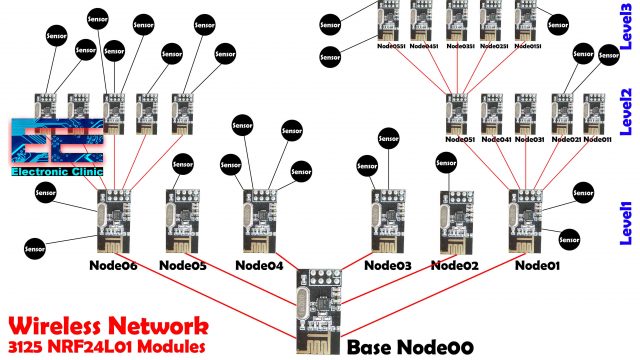
You might be thinking about the maximum number of NRF24L01 Transceiver modules that can be used in a wireless Sensor network. A single NRF24L01 module can actively listen up to 6 other modules at the same time.
where one node is the base, and all other nodes are children of either that node or of another. Each node can have up to 5 children, and this can go 5 levels deep, which means we can create a network of total 3125 nodes. Each node must be defined with a 15-bit address, which precisely describes the position of the node within the tree.
NRF24L01 Modules Two way communication, Circuit Diagrams:
NRF24L01 Node00, circuit Diagram:
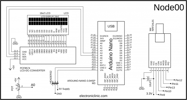
This is the circuit diagram of the Node00. A potentiometer is connected with the Analog pin A0. A decoupling capacitor of 10uf is connected with the VCC and GND pins of the NRF24L01 module. The VCC and GND pins are connected with the Arduino’s 3.3V and GND pins. CE is connected with Pin9, CSN is connected with Pin10, SCK is connected with 13, MOSI is connected with Pin11, and the MISO pin is connected with Pin12 of the Arduino.
I2C supported 16×2 LCD SCL and SDA pins are connected with the Arduino’s Analog pins A5 and A4. While the VCC and GND pins of the LCD module are connected with the Arduino’s 5V and GND.
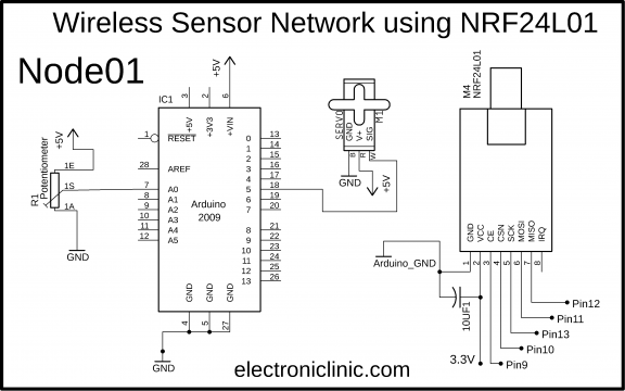
NRF24L01 Node01, circuit Diagram:
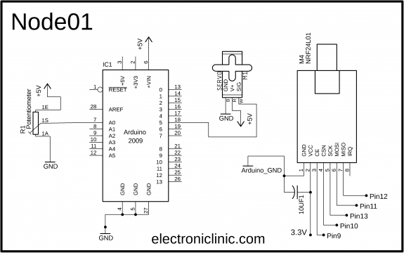
This is the circuit diagram of the Node01. The NRF24L01 and Potentiometer connection with the Arduino remain exactly the same. The signal wire of the Servo motor is connected with the PWM pin 5 of the Arduino. While the power supply wires of the Servo motor are connected with the 5V and GND. For the best performance you can add a decoupling capacitor with the power supply pins of the Servo motor.
Interfacing:
I connected all the electronics as per the circuit diagram. I have already explained the PCB designing and soldering in my previous tutorial. Our circuits are ready for the programming. Now, let’s take a look at the programming of the Node00 and Node01.
NRF24L01 Two Way Communication, Arduino Programming:
As usual before you start the programming first of all, make sure you download all the necessary libraries. You will also need the RF24 and RF24Network libraries. Let’s take a look at the Node00 programming.
NRF24L01 Node00 Arduino Code:
|
1 2 3 4 5 6 7 8 9 10 11 12 13 14 15 16 17 18 19 20 21 22 23 24 25 26 27 28 29 30 31 32 33 34 35 36 37 38 39 40 41 42 43 44 45 46 47 48 49 50 51 52 53 54 55 56 57 58 59 60 61 62 63 64 65 66 67 68 69 70 71 72 73 74 75 76 77 78 79 80 81 82 83 84 85 86 87 88 89 90 91 92 93 94 95 96 97 98 |
// Master Node00 #include #include #include #include #include #include LiquidCrystal_I2C lcd(0x27,16,2); //0x27 is the i2c address, while 16 = columns, and 2 = rows. SimpleTimer timer; SimpleTimer timer1; RF24 radio(9, 10); // nRF24L01 (CE,CSN) RF24Network network(radio); // Include the radio in the network const uint16_t this_node = 00; // Address of our node in Octal format const uint16_t node01 = 01; unsigned long data[6]; // number of sensors unsigned long data1; unsigned long data2; void setup() { Serial.begin(9600); SPI.begin(); radio.begin(); network.begin(90, this_node); //(channel, node address) radio.setDataRate(RF24_2MBPS); lcd.init(); //Init the LCD lcd.backlight(); //Activate backlight lcd.home(); timer.setInterval(200L, lcdDisplay); timer1.setInterval(50L, Sensor1Send); } void loop() { timer.run(); timer1.run(); network.update(); DataReceive(); } void DataReceive() { while ( network.available() ) { // Is there any incoming data? RF24NetworkHeader header; network.read(header, &data, sizeof(data)); // Read the incoming data if (header.from_node == 1) { // If data comes from Node 01 data1 = data[0]; Serial.println("Data from Node01:"); Serial.println(data1); } if (header.from_node == 2) { // If data comes from Node 02 data2 = data[0]; } } } void Sensor1Send() { unsigned long potValue = analogRead(A0); // Read the potentiometer value potValue = map(potValue, 0,1023,0,180); data[0] = potValue; RF24NetworkHeader header7(node01); bool ok = network.write(header7, &data, sizeof(data)); // Send the data } void lcdDisplay() { lcd.clear(); lcd.setCursor(0,0); lcd.print("Node01:"); lcd.print(data1); /* lcd.setCursor(0,1); lcd.print("T2_D2:"); lcd.print(data2); */ } |
Code Explanation:
Maximum of the code I have already explained in my previous tutorial.
const uint16_t this_node = 00; // Address of our node in Octal format
const uint16_t node01 = 01;
These are the nodes addresses.
unsigned long data[6]; // number of sensors
I defined this array for storing the sensors values, in my case I store the potentiometer value. I will store the potentiometer value at location 0 in the data array. You can connect more sensors and store the values at location 1, 2, 3 and so on. If you want to use more sensors simply increase the array size.
unsigned long data1;
unsigned long data2;
The variables data1 and data2 are used to store the values coming from the Node01. Rest of the programming is exactly the same as explained in my previous tutorial. I am using the same DataReceive() function and the same Sensor1Send() function. This time I only mapped the value as per the Servo Motor. I am also using the same lcdDisplay() function which I am using to display the Potentiometer value received from the Node01. Now, let’s take a look at the Node01 programming.
NRF24L01 Node01 Arduino Code:
|
1 2 3 4 5 6 7 8 9 10 11 12 13 14 15 16 17 18 19 20 21 22 23 24 25 26 27 28 29 30 31 32 33 34 35 36 37 38 39 40 41 42 43 44 45 46 47 48 49 50 51 52 53 54 55 56 57 58 59 60 61 62 63 64 65 66 67 68 69 70 71 72 73 74 75 76 77 78 79 80 81 82 83 84 85 86 87 88 89 90 91 92 93 94 95 |
// Node01 #include #include #include #include #include #include #include LiquidCrystal_I2C lcd(0x27,16,2); //0x27 is the i2c address, while 16 = columns, and 2 = rows. Servo myservo; SimpleTimer timer; SimpleTimer timer1; RF24 radio(9, 10); // nRF24L01 (CE,CSN) RF24Network network(radio); // Include the radio in the network const uint16_t this_node = 01; // Address of this node in Octal format const uint16_t node00 = 00; unsigned long data[6]; // number of sensors unsigned long data1; unsigned long data2; void setup() { Serial.begin(9600); SPI.begin(); radio.begin(); network.begin(90, this_node); //(channel, node address) radio.setDataRate(RF24_2MBPS); lcd.init(); //Init the LCD lcd.backlight(); //Activate backlight lcd.home(); timer.setInterval(200L, lcdDisplay); timer1.setInterval(50L, Sensor1Send); myservo.attach(5); // servo motor connected here } void loop() { timer.run(); timer1.run(); network.update(); DataReceive(); } void Sensor1Send() { unsigned long potValue = analogRead(A0); // Read the potentiometer value data[0] = potValue; RF24NetworkHeader header7(node00); bool ok = network.write(header7, &data, sizeof(data)); // Send the data } void DataReceive() { while ( network.available() ) { // Is there any incoming data? RF24NetworkHeader header; network.read(header, &data, sizeof(data)); // Read the incoming data if (header.from_node == 0) { // If data comes from Node 01 data1 = data[0]; myservo.write(data1); //Serial.println("Master Node00:"); //Serial.println(data1); } if (header.from_node == 2) { // If data comes from Node 02 data2 = data[0]; } } } void lcdDisplay() { lcd.clear(); lcd.setCursor(0,0); lcd.print("T1_D1:"); lcd.print(data1); lcd.setCursor(0,1); lcd.print("T2_D2:"); lcd.print(data2); } |
Code Explanation:
The Node01 programming is exactly the same. The only modification is the addition of the Servo Motor. In the DataReceive() function I used an IF condition to check if the data is received from the Node00 and then used the received data to control the angle of the Servo Motor. Everything else remains exactly the same.
NRF24L01 Two Way Communication, Testing:
This is not a network, but a wireless two way communication system based on the NRF24L01 modules. The reason I started with only two NRF24L01 modules is to help you easily understand the two way communication. So, after successfully transmitting and receiving the data, now it’s time to make a wireless sensor network using multiple NRF24L01 Transceiver modules. I will do it only for three nodes, but you can increase the number of nodes in the same way as I am about to add another node011. For the practical demonstration watch video tutorial given at the end of this article.
NRF24L01 based Wireless Sensor Network, Circuit Diagrams:
After the successful testing of the two way communication system using Arduino and a pair of NRF24L01 Transceiver module, now we are ready to make the Wireless Sensor Network using multiple NRF24L01 Modules and Arduino.
Wireless Sensor Network, Node00 Circuit Diagram:

Node00 remains exactly the same, this time I connected an LED with Pin2 of the Arduino.
Wireless Sensor Network, Node01 Circuit Diagram:
Node01 remains exactly the same, I did no changes.
Wireless Sensor Network, Node011 Circuit Diagram:
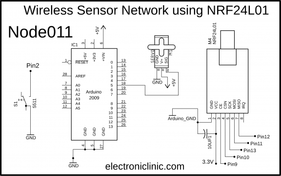
Node011 is just like the Node01, this time I replaced the Potentiometer with a pushbutton. Now, let’s take a look at the programming.
NRF24L01 based Wireless Sensor Network, Arduino Codes:
The codes are pretty much the same.
NRF24L01 based Wireless Sensor Network, Node00 Code:
|
1 2 3 4 5 6 7 8 9 10 11 12 13 14 15 16 17 18 19 20 21 22 23 24 25 26 27 28 29 30 31 32 33 34 35 36 37 38 39 40 41 42 43 44 45 46 47 48 49 50 51 52 53 54 55 56 57 58 59 60 61 62 63 64 65 66 67 68 69 70 71 72 73 74 75 76 77 78 79 80 81 82 83 84 85 86 87 88 89 90 91 92 93 94 95 96 97 98 99 100 |
// Master Node00 #include #include #include #include #include #include LiquidCrystal_I2C lcd(0x27,16,2); //0x27 is the i2c address, while 16 = columns, and 2 = rows. SimpleTimer timer; SimpleTimer timer1; RF24 radio(9, 10); // nRF24L01 (CE,CSN) RF24Network network(radio); // Include the radio in the network const uint16_t this_node = 00; // Address of our node in Octal format const uint16_t node01 = 01; unsigned long data[6]; // number of sensors unsigned long data1; unsigned long data2; int LED = 2; void setup() { Serial.begin(9600); SPI.begin(); radio.begin(); network.begin(90, this_node); //(channel, node address) radio.setDataRate(RF24_2MBPS); lcd.init(); //Init the LCD lcd.backlight(); //Activate backlight lcd.home(); timer.setInterval(1000L, lcdDisplay); timer1.setInterval(50L, Sensor1Send); pinMode(3, OUTPUT); digitalWrite(3, HIGH); // 5v to the variable resistor pinMode(LED, OUTPUT); } void loop() { timer.run(); timer1.run(); network.update(); DataReceive(); } void DataReceive() { while ( network.available() ) { // Is there any incoming data? RF24NetworkHeader header; network.read(header, &data, sizeof(data)); // Read the incoming data if (header.from_node == 1) { // If data comes from Node 01 data1 = data[0]; // pot value data2 = data[3]; // push button state if(data2 == 1) { digitalWrite(LED,LOW); } if(data2 == 0) { digitalWrite(LED,HIGH); } } } } void Sensor1Send() { unsigned long potValue = analogRead(A0); // Read the potentiometer value potValue = map(potValue, 0,1023,0,180); data[0] = potValue; RF24NetworkHeader header7(node01); bool ok = network.write(header7, &data, sizeof(data)); // Send the data } void lcdDisplay() { ; } |
NRF24L01 based Wireless Sensor Network, Node01 Code:
|
1 2 3 4 5 6 7 8 9 10 11 12 13 14 15 16 17 18 19 20 21 22 23 24 25 26 27 28 29 30 31 32 33 34 35 36 37 38 39 40 41 42 43 44 45 46 47 48 49 50 51 52 53 54 55 56 57 58 59 60 61 62 63 64 65 66 67 68 69 70 71 72 73 74 75 76 77 78 79 80 81 82 83 84 85 86 87 88 89 90 91 92 93 94 95 96 97 98 99 100 101 102 103 104 105 106 |
// Node01 #include <RF24.h> #include <RF24Network.h> #include <SPI.h> #include <Wire.h> #include <SimpleTimer.h> #include <LiquidCrystal_I2C.h> #include<Servo.h> LiquidCrystal_I2C lcd(0x27,16,2); //0x27 is the i2c address, while 16 = columns, and 2 = rows. Servo myservo; SimpleTimer timer; SimpleTimer timer1; RF24 radio(9, 10); // nRF24L01 (CE,CSN) RF24Network network(radio); // Include the radio in the network const uint16_t this_node = 01; // Address of this node in Octal format const uint16_t node00 = 00; const uint16_t node011 = 011; unsigned long data[6]; // number of sensors unsigned long dataa[6]; unsigned long data1; unsigned long data2; void setup() { Serial.begin(9600); SPI.begin(); radio.begin(); network.begin(90, this_node); //(channel, node address) radio.setDataRate(RF24_2MBPS); lcd.init(); //Init the LCD lcd.backlight(); //Activate backlight lcd.home(); timer.setInterval(1000L, lcdDisplay); timer1.setInterval(50L, Sensor1Send); myservo.attach(5); // servo motor connected here } void loop() { timer.run(); timer1.run(); network.update(); DataReceive(); } void Sensor1Send() { unsigned long potValue = analogRead(A0); // Read the potentiometer value potValue = map(potValue, 0,1023,0,180); data[0] = potValue; RF24NetworkHeader header7(node00); bool ok = network.write(header7, &data, sizeof(data)); // Send the data RF24NetworkHeader header8(node011); network.write(header8, &data, sizeof(data)); // Send the data } void DataReceive() { while ( network.available() ) { // Is there any incoming data? RF24NetworkHeader header; network.read(header, &data, sizeof(data)); // Read the incoming data if (header.from_node == 0) { // If data comes from Node00 data1 = data[0]; myservo.write(data1); //Serial.println("Master Node00:"); //Serial.println(data1); } if (header.from_node == 9) // 011 octal equals to 9 in decimal { // If data comes from Node011 data2 = data[2]; dataa[3] = data2; RF24NetworkHeader header9(node00); network.write(header9, &dataa, sizeof(data)); // Send the data } } } void lcdDisplay() { ; /* lcd.clear(); lcd.setCursor(0,0); lcd.print("T1_D1:"); lcd.print(data1); lcd.setCursor(0,1); lcd.print("T2_D2:"); lcd.print(data2); */ } |
NRF24L01 based Wireless Sensor Network, Node011 Code:
|
1 2 3 4 5 6 7 8 9 10 11 12 13 14 15 16 17 18 19 20 21 22 23 24 25 26 27 28 29 30 31 32 33 34 35 36 37 38 39 40 41 42 43 44 45 46 47 48 49 50 51 52 53 54 55 56 57 58 59 60 61 62 63 64 65 66 67 68 69 70 71 72 73 74 75 76 77 78 79 80 81 82 83 84 85 86 87 88 89 90 91 92 93 94 95 96 |
// Node011 #include <RF24.h> #include <RF24Network.h> #include <SPI.h> #include <Wire.h> #include <SimpleTimer.h> #include <LiquidCrystal_I2C.h> #include<Servo.h> LiquidCrystal_I2C lcd(0x27,16,2); //0x27 is the i2c address, while 16 = columns, and 2 = rows. Servo myservo; SimpleTimer timer; SimpleTimer timer1; RF24 radio(9, 10); // nRF24L01 (CE,CSN) RF24Network network(radio); // Include the radio in the network const uint16_t this_node = 011; // Address of this node in Octal format const uint16_t node01 = 01; unsigned long data[6]; // number of sensors unsigned long data1; unsigned long data2; int Bstate; void setup() { Serial.begin(9600); SPI.begin(); radio.begin(); network.begin(90, this_node); //(channel, node address) radio.setDataRate(RF24_2MBPS); lcd.init(); //Init the LCD lcd.backlight(); //Activate backlight lcd.home(); timer.setInterval(1000L, lcdDisplay); timer1.setInterval(100L, Sensor1Send); pinMode(2, INPUT_PULLUP); // pushbutton myservo.attach(5); // servo motor connected here } void loop() { timer.run(); timer1.run(); network.update(); DataReceive(); } void Sensor1Send() { Bstate = digitalRead(2); data[2] = Bstate; RF24NetworkHeader header7(node01); bool ok = network.write(header7, &data, sizeof(data)); // Send the data } void DataReceive() { while ( network.available() ) { // Is there any incoming data? RF24NetworkHeader header; network.read(header, &data, sizeof(data)); // Read the incoming data if (header.from_node == 1) { // If data comes from Node 01 data1 = data[0]; myservo.write(data1); //Serial.println("From Node01:"); //Serial.println(data1); } } } void lcdDisplay() { ; /* lcd.clear(); lcd.setCursor(0,0); lcd.print("T1_D1:"); lcd.print(data1); lcd.setCursor(0,1); lcd.print("T2_D2:"); lcd.print(data2); */ } |
Code Explanation:
Let’s take a look at the code of Node01 which is the intermediate node as the data communication between the Sensor Node00 and the Sensor Node011 takes place through this node. As you can see this time I added another Node011. I also added another data array. Everything else remains exactly the same. In the Sensor1send() function. I am sending the data to Sensor Node00 and also to the Sensor Node011.
Inside the DataReceive() function I used two if conditions. The first if condition checks if the data is received from the Wireless Sensor node00 which is used to control the servo motor. While the second if condition is used to check if the data is received from the Wireless Sensor node011 which is equal to 9 in decimal. We read the button state which is stored at location 2 in the data array and store it in data2 variable. Then we store this value in the other data array at location 3 and send it to the Node00 where it is used to control the LED.
You can use the same code to make another node, you will only need to change the addresses as per your requirement.
I uploaded all the three codes and successfully transferred the data among all the three nodes. You can practically see everything in video given below. If you have any question regarding this article let me know in a comment.
Watch Video Tutorial:
Discover more from Electronic Clinic
Subscribe to get the latest posts sent to your email.


I would like to contact you on further information on your project . Could you please contact me so I could explain in detail, thanks.