Load balancing of a 3 Phase Transformer, Arduino 3 Phase Load Balancer
Last Updated on February 25, 2024 by Engr. Shahzada Fahad
Table of Contents
3 Phase Transformer Load Balancing, Project Description:
Load balancing of a 3 phase transformer- In this Tutorial, you will learn how to make a 3 phase transformer consumers load monitoring and load balancing or load shifting project using Arduino, 433Mhz Radio Frequency Transmitter and Receivers.
In this project, two applications will be used.
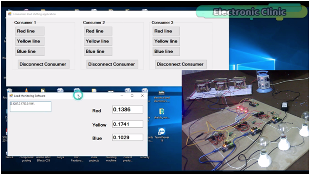
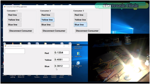
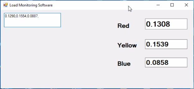
This application will be used for monitoring all the three phases Red, Yellow, and Blue in Real-time.
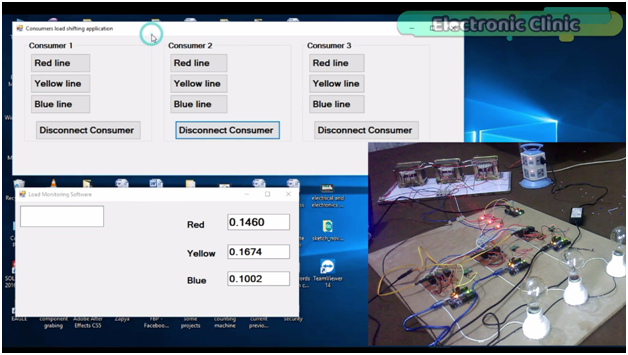
While with the help of this application any consumer can be connected with any of the 3 phases. Let me show you this practically. Let’s connect consumer 2 with the Yellow phase as you can see the bulb is turned ON, and you can also see an increase in the value.
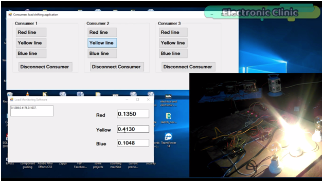
Let’s connect consumer three with the yellow phase as well.

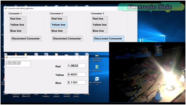
You can see the bulb is turned on and the value is further increased. As you can see currently the load on the yellow phase is more than the red phase and blue phase. Now to reduce load on the yellow phase we can shift consumer 2 or consumer3 on any other phase. let’s connect consumer 3 with the red phase. A

As you can see the load on the yellow phase is reduced, this way we can do the load balancing. In case of any emergency a consumer can be disconnected.
Now let’s connect consumer 3 with the Blue phase.
As you can see the value on the Blue Phase is increased. let’s connect consumer 2 with the blue phase as well.

You can see the value is further increased. Now the load on the blue phase is greater than the other two phases, to reduce load on the blue phase we can shift the consumer load on any other phase. All these consumers are wirelessly controlled using 433Mhz Radiofrequency Transmitters and receivers. One transmitter is used to send commands to 3 receiver modules.
This is the 3rd version of the 3 phase transformer load monitoring system.
While in the first version; I designed an application in vb.net and used this application to monitor all the three phases of the 3 phase transformer prototype model. The transformer wiring, soldering, the acs712 current sensors connections, soldering and interfacing is already explained in very detail.
3 Phase Transformer Load Monitoring: Version 1
In the second version, I used the Blynk application for monitoring all the three phases in real-time from anywhere around the world using a cell phone, Arduino, and Nodemcu esp8266 wifi module.
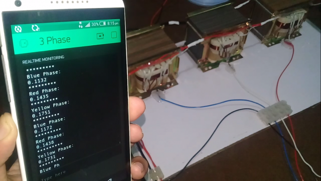
IOT 3 Phase Transformer Load Monitoring using Nodemcu ESP266 and Arduino: Version 2
As this is the version 3 of the 3 phase transformer load monitoring and load balancing system, this project is around 70% based on the version1, as I will be using the same connections and the same computer application for monitoring all the three phases.
For the best understanding, I recommend you should watch my first tutorial on 3 phase transformer load monitoring system and then you can resume from here. As in this tutorial, I will only explain the modifications which are
- Complete circuit diagram of the “ Load balancing of a 3 phase transformer “
- Interfacing
- Consumers load shifting computer application programming
- Transmitter programming and
- Receivers programming (Consumers)
For the Step by Step explanation and practical demonstration watch Video given at the end of this Article and Don’t forget to subscribe to my YouTube channel.
Cautions: This Project makes use of the 220/230Vac, do not touch any wires while the transformers are turned ON may result in a heavy shock or it can be lethal.
Amazon Links:
Other Tools and Components:
Super Starter kit for Beginners
PCB small portable drill machines
DISCLAIMER:
Please Note: these are affiliate links. I may make a commission if you buy the components through these links. I would appreciate your support in this way!
3 phase load balancing Circuit Diagram:

This is the circuit diagram which I used in version 1, which I have already explained in very detailed and the link is given above. As you can see in the Circuit Diagram above three acs712 current sensors are connected with the analog pins A1, A2, and A3.
Three Phases coming from the Transformer are labeled as Red, Yellow, and Blue.
The three bulbs connected with the Red, Yellow, and Blue Phases. Arduino calculates the load and then send the values to the computer application.

While this is the modified circuit diagram used in Version2 of the 3 phase transformer load monitoring system using Nodemcu esp8266 wifi module and Arduino. Regulated power supply is based on the lm7805 voltage regulator.
Two 470uf capacitors are connected at the input and output of the regulator. A 330-ohm resistor connected in series with a 2.5v led. This is a current limiting resistor, while J1 is the dc female power Jack; this is where we can connect a 12v adaptor or battery.
The output of the 7805 Regulator is connected with the Vin pin of the Nodemcu module while the ground is connected with the ground. Connect the TX pin of the Nodemcu module with the RX pin of the Arduino and connect the RX pin of the Nodemcu module with the TX pin of the Arduino and also make sure you connect the ground pin of the Nodemcu module with the ground pin of the Arduino. So this is the only modification that I made in the 2nd version.
While this is the final modified circuit diagram in which three consumers are added. The consumer supply is controlled using a transmitter which will be connected with the computer application. Let’s start with the transmitter side, as you can see the 433Mhz RF transmitter data pin is connected with the Arduino’s pin number 12 while the transmitter 5v and GND pins are connected with the Arduino’s 5v and Ground.
The 433Mhz RF receiver data pin is connected with the Arduino’s pin number 11 while the receiver 5v and GND pins are connected with the Arduino’s 5v and ground. Three channel relay module is connected with pin number 8, 9 and 10. These relays are 12v and are of the type “SPDT” Single pole and double throw”. These relays are controlled with the help of the driver circuits which consists of the 2n2222 NPN transistors and 10k resistors; watch my tutorial on relay driver circuit design calculations. The Common legs of the relays are connected together and then connected with the load, while the normally open legs of the relays are connected with the Red, Yellow, and Blue phases. With the help of these relays consumer1 can be connected with any phase…consumer2 and consumer 3 also has the same connections. For further clarification you can watch video given at the End of this Article.
3 phase load balancing Programming:
Transmitter and Receivers Programming:
|
1 2 3 4 5 6 7 8 9 10 11 12 13 14 15 16 17 18 19 20 21 22 23 24 25 26 27 28 29 30 31 32 33 34 35 36 37 38 39 40 41 42 43 44 45 46 47 48 |
// transmitter.pde // connect vcc of the transmitter and receiver to 5v on arduino #include <VirtualWire.h> #include <String.h> const int led_pin = 11; const int transmit_pin = 12; const int transmit_en_pin = 3; String str; char cstr[27]; void setup() { // Initialise the IO and ISR vw_set_tx_pin(transmit_pin); Serial.begin(9600); vw_setup(2000); // Bits per sec pinMode(led_pin, OUTPUT); pinMode(ldr, INPUT); } byte count = 1; void loop() { if(Serial.available()>0) { char message = Serial.read(); str = String(message); str.toCharArray(cstr,27); // msg[6] = count; digitalWrite(led_pin, HIGH); // Flash a light to show transmitting vw_send((uint8_t *)cstr, 1); // change this number according to the sensor values vw_wait_tx(); // Wait until the whole message is gone digitalWrite(led_pin, LOW); count = count + 1; } } |
Receiver1 or Consumer1 Arduino Programming:
|
1 2 3 4 5 6 7 8 9 10 11 12 13 14 15 16 17 18 19 20 21 22 23 24 25 26 27 28 29 30 31 32 33 34 35 36 37 38 39 40 41 42 43 44 45 46 47 48 49 50 51 52 53 54 55 56 57 58 59 60 61 62 63 64 65 66 67 68 69 70 71 72 73 74 75 76 77 78 79 80 81 82 83 84 85 86 87 88 89 90 91 92 93 94 95 96 97 98 |
// receiver.pde // FOR CONSUMER 1 /* command a to activate red line command b to activate yellow line command c to activate blue line command d to disconnect the consumer 1 */ #include <VirtualWire.h> const int receive_pin = 11; int red = 8; // relay for red line int yellow = 9; // relay for yellow line int blue = 10; // relay for blue line void setup() { delay(1000); Serial.begin(9600); // Debugging only Serial.println("setup"); // Initialise the IO and ISR vw_set_rx_pin(receive_pin); vw_set_ptt_inverted(true); // Required for DR3100 vw_setup(2000); // Bits per sec vw_rx_start(); // Start the receiver PLL running pinMode(red, OUTPUT); pinMode(yellow, OUTPUT); pinMode(blue, OUTPUT); digitalWrite(red, LOW); digitalWrite(yellow, LOW); digitalWrite(blue, LOW); delay(1000); } void loop() { uint8_t buf[VW_MAX_MESSAGE_LEN]; uint8_t buflen = VW_MAX_MESSAGE_LEN; if (vw_get_message(buf, &buflen)) // Non-blocking { int i; for (i = 0; i < buflen; i++) { char c = (buf[i]); Serial.print(c); if( c == 'a') // consumer1 red line { digitalWrite(yellow, LOW); digitalWrite(blue, LOW); delay(500); digitalWrite(red, HIGH); delay(1000); } if( c == 'b') // consumer1 yellow line { digitalWrite(red, LOW); digitalWrite(blue, LOW); delay(500); digitalWrite(yellow, HIGH); delay(1000); } if(c == 'c') //consumer1 blue line { digitalWrite(red, LOW); digitalWrite(yellow, LOW); delay(500); digitalWrite(blue, HIGH); delay(1000); } if(c == 'd') //consumer1 full disconnection { digitalWrite(red, LOW); digitalWrite(yellow, LOW); digitalWrite(blue, LOW); delay(1000); } } } } |
Receiver2 or Consumer2 Arduino Programming:
|
1 2 3 4 5 6 7 8 9 10 11 12 13 14 15 16 17 18 19 20 21 22 23 24 25 26 27 28 29 30 31 32 33 34 35 36 37 38 39 40 41 42 43 44 45 46 47 48 49 50 51 52 53 54 55 56 57 58 59 60 61 62 63 64 65 66 67 68 69 70 71 72 73 74 75 76 77 78 79 80 81 82 83 84 85 86 87 88 89 90 91 92 93 94 95 96 97 98 |
// receiver.pde // FOR CONSUMER 2 /* command e to activate red line command f to activate yellow line command g to activate blue line command h to disconnect the consumer 2 */ #include <VirtualWire.h> const int receive_pin = 11; int red = 8; // relay for red line int yellow = 9; // relay for yellow line int blue = 10; // relay for blue line void setup() { delay(1000); Serial.begin(9600); // Debugging only Serial.println("setup"); // Initialise the IO and ISR vw_set_rx_pin(receive_pin); vw_set_ptt_inverted(true); // Required for DR3100 vw_setup(2000); // Bits per sec vw_rx_start(); // Start the receiver PLL running pinMode(red, OUTPUT); pinMode(yellow, OUTPUT); pinMode(blue, OUTPUT); digitalWrite(red, LOW); digitalWrite(yellow, LOW); digitalWrite(blue, LOW); delay(1000); } void loop() { uint8_t buf[VW_MAX_MESSAGE_LEN]; uint8_t buflen = VW_MAX_MESSAGE_LEN; if (vw_get_message(buf, &buflen)) // Non-blocking { int i; for (i = 0; i < buflen; i++) { char c = (buf[i]); Serial.print(c); if( c == 'e') // consumer2 red line { digitalWrite(yellow, LOW); digitalWrite(blue, LOW); delay(500); digitalWrite(red, HIGH); delay(1000); } if( c == 'f') // consumer2 yellow line { digitalWrite(red, LOW); digitalWrite(blue, LOW); delay(500); digitalWrite(yellow, HIGH); delay(1000); } if(c == 'g') //consumer2 blue line { digitalWrite(red, LOW); digitalWrite(yellow, LOW); delay(500); digitalWrite(blue, HIGH); delay(1000); } if(c == 'h') //consumer1 full disconnection { digitalWrite(red, LOW); digitalWrite(yellow, LOW); digitalWrite(blue, LOW); delay(1000); } } } } |
Receiver3 or Consumer3 Arduino Programming:
|
1 2 3 4 5 6 7 8 9 10 11 12 13 14 15 16 17 18 19 20 21 22 23 24 25 26 27 28 29 30 31 32 33 34 35 36 37 38 39 40 41 42 43 44 45 46 47 48 49 50 51 52 53 54 55 56 57 58 59 60 61 62 63 64 65 66 67 68 69 70 71 72 73 74 75 76 77 78 79 80 81 82 83 84 85 86 87 88 89 90 91 92 93 94 95 96 97 98 |
// receiver.pde // FOR CONSUMER 3 /* command i to activate red line command j to activate yellow line command k to activate blue line command l to disconnect the consumer 3 */ #include <VirtualWire.h> const int receive_pin = 11; int red = 8; // relay for red line int yellow = 9; // relay for yellow line int blue = 10; // relay for blue line void setup() { delay(1000); Serial.begin(9600); // Debugging only Serial.println("setup"); // Initialise the IO and ISR vw_set_rx_pin(receive_pin); vw_set_ptt_inverted(true); // Required for DR3100 vw_setup(2000); // Bits per sec vw_rx_start(); // Start the receiver PLL running pinMode(red, OUTPUT); pinMode(yellow, OUTPUT); pinMode(blue, OUTPUT); digitalWrite(red, LOW); digitalWrite(yellow, LOW); digitalWrite(blue, LOW); delay(1000); } void loop() { uint8_t buf[VW_MAX_MESSAGE_LEN]; uint8_t buflen = VW_MAX_MESSAGE_LEN; if (vw_get_message(buf, &buflen)) // Non-blocking { int i; for (i = 0; i < buflen; i++) { char c = (buf[i]); Serial.print(c); if( c == 'i') // consumer3 red line { digitalWrite(yellow, LOW); digitalWrite(blue, LOW); delay(500); digitalWrite(red, HIGH); delay(1000); } if( c == 'j') // consumer3 yellow line { digitalWrite(red, LOW); digitalWrite(blue, LOW); delay(500); digitalWrite(yellow, HIGH); delay(1000); } if(c == 'k') //consumer3 blue line { digitalWrite(red, LOW); digitalWrite(yellow, LOW); delay(500); digitalWrite(blue, HIGH); delay(1000); } if(c == 'l') //consumer3 full disconnection { digitalWrite(red, LOW); digitalWrite(yellow, LOW); digitalWrite(blue, LOW); delay(1000); } } } } |
Load Monitoring Arduino Programming:
|
1 2 3 4 5 6 7 8 9 10 11 12 13 14 15 16 17 18 19 20 21 22 23 24 25 26 27 28 29 30 31 32 33 34 35 36 37 38 39 40 41 42 43 44 45 46 47 48 49 50 51 52 53 54 55 56 57 58 59 60 61 62 63 64 65 66 67 68 69 70 71 72 73 74 75 76 77 78 79 80 81 82 83 84 85 86 87 88 89 90 91 92 93 |
#include <stdlib.h> String textForSMS; char buff[10]; const unsigned long sampleTime = 100000UL; // sample over 100ms, it is an exact number of cycles for both 50Hz and 60Hz mains const unsigned long numSamples = 250UL; // choose the number of samples to divide sampleTime exactly, but low enough for the ADC to keep up const unsigned long sampleInterval = sampleTime/numSamples; // the sampling interval, must be longer than then ADC conversion time const int adc_zero = 510; // Red line const int currentPin = 1; // current sensor connected here analog pin A1 float rms; // Yellow line const int currentPin2 = 2; // analog pin A2 float rms2; // Blue Line const int currentPin3 = 3; // analog pin A3 float rms3; String stringrms; String stringrms2; String stringrms3; void setup() { Serial.begin(9600); pinMode(currentPin, INPUT); pinMode(currentPin2, INPUT); pinMode(currentPin3, INPUT); } void loop() { RYB(); // red yellow blue lines checking, its a calling function. textForSMS = textForSMS + stringrms + "," + stringrms2 + "," + stringrms3 +","; Serial.println(textForSMS); delay(1000); textForSMS = ""; } void RYB() // red , yellow , blue lines { unsigned long currentAcc = 0; unsigned int count = 0; unsigned long currentAcc2 = 0; unsigned long currentAcc3 = 0; unsigned long prevMicros = micros() - sampleInterval ; while (count < numSamples) { if (micros() - prevMicros >= sampleInterval) { int adc_raw = analogRead(currentPin) - adc_zero; // user 1 currentAcc += (unsigned long)(adc_raw * adc_raw); // user 1 int adc_raw2 = analogRead(currentPin2) - adc_zero; // user2 currentAcc2 += (unsigned long)(adc_raw2 * adc_raw2); // user 2 int adc_raw3 = analogRead(currentPin3) - adc_zero; // illegal user currentAcc3 += (unsigned long)(adc_raw3 * adc_raw3); // illegal user ++count; prevMicros += sampleInterval; } } rms = sqrt((float)currentAcc/(float)numSamples) * (75.7576 / 1024.0); delay(100); rms2 = sqrt((float)currentAcc2/(float)numSamples) * (75.7576 / 1024.0); delay(100); rms3 = sqrt((float)currentAcc3/(float)numSamples) * (75.7576 / 1024.0); delay(100); stringrms = dtostrf(rms, 1, 4, buff); stringrms2 = dtostrf(rms2, 1, 4, buff); stringrms3 = dtostrf(rms3, 1, 4, buff); //Serial.println("\n"); delay(1000); //Serial.println(currentAcc); // delay(1000); } |
Load Monitoring Application Programming designed in VB.net:
|
1 2 3 4 5 6 7 8 9 10 11 12 13 14 15 16 17 18 19 20 21 22 23 24 25 26 27 28 29 30 31 32 33 34 35 36 37 38 39 40 41 42 43 44 45 46 47 48 49 50 51 52 53 54 |
Imports System.IO Imports System.IO.Ports Public Class Form1 Dim value1 As Integer Private Sub Form1_Load(ByVal sender As System.Object, ByVal e As System.EventArgs) Handles MyBase.Load SerialPort1.Close() SerialPort1.PortName = "com32" SerialPort1.BaudRate = "9600" SerialPort1.DataBits = 8 SerialPort1.Parity = Parity.None SerialPort1.StopBits = StopBits.One SerialPort1.Handshake = Handshake.None SerialPort1.Encoding = System.Text.Encoding.Default SerialPort1.Open() End Sub Private Sub Timer1_Tick(ByVal sender As System.Object, ByVal e As System.EventArgs) Handles Timer1.Tick Dim s As String s = TextBox1.Text + "," + "," + "," + "," Dim somestring() As String ' Split string based on comma somestring = s.Split(New Char() {","c}) TextBox2.Text = somestring(0) ' value1 = Convert.ToDecimal(TextBox2.Text) TextBox3.Text = somestring(1) TextBox4.Text = somestring(2) TextBox1.Text = "" End Sub Private Sub DataReceived(ByVal sender As Object, ByVal e As SerialDataReceivedEventArgs) Handles SerialPort1.DataReceived Try Dim mydata As String = "" mydata = SerialPort1.ReadExisting() If TextBox1.InvokeRequired Then TextBox1.Invoke(DirectCast(Sub() TextBox1.Text &= mydata, MethodInvoker)) Else TextBox1.Text &= mydata End If Catch ex As Exception MessageBox.Show(ex.Message) End Try End Sub End Class |
Consumers load Balancing or Load shifting Application Programming:
|
1 2 3 4 5 6 7 8 9 10 11 12 13 14 15 16 17 18 19 20 21 22 23 24 25 26 27 28 29 30 31 32 33 34 35 36 37 38 39 40 41 42 43 44 45 46 47 48 49 50 51 52 53 54 55 56 57 58 59 60 61 62 63 64 65 66 67 68 69 70 71 72 73 74 75 76 77 78 79 80 81 82 83 84 85 86 87 88 89 90 91 92 93 94 95 96 97 98 99 100 101 102 103 104 105 106 107 108 109 110 111 112 113 114 115 116 117 118 119 120 121 122 123 124 125 126 127 128 129 130 131 132 133 134 135 136 137 |
Imports System.IO Imports System.IO.Ports Public Class Form1 Private Sub Form1_Load(ByVal sender As System.Object, ByVal e As System.EventArgs) Handles MyBase.Load SerialPort1.Close() SerialPort1.PortName = "com24" SerialPort1.BaudRate = "9600" SerialPort1.DataBits = 8 SerialPort1.Parity = Parity.None SerialPort1.StopBits = StopBits.One SerialPort1.Handshake = Handshake.None SerialPort1.Encoding = System.Text.Encoding.Default End Sub Private Sub CheckBox1_CheckedChanged(sender As System.Object, e As System.EventArgs) Handles CheckBox1.CheckedChanged If CheckBox1.Checked = True Then SerialPort1.Open() SerialPort1.Write("b") SerialPort1.Close() End If End Sub Private Sub CheckBox2_CheckedChanged(sender As System.Object, e As System.EventArgs) Handles CheckBox2.CheckedChanged If CheckBox2.Checked = True Then SerialPort1.Open() SerialPort1.Write("a") SerialPort1.Close() End If End Sub Private Sub CheckBox3_CheckedChanged(sender As System.Object, e As System.EventArgs) Handles CheckBox3.CheckedChanged If CheckBox3.Checked = True Then SerialPort1.Open() SerialPort1.Write("c") SerialPort1.Close() End If End Sub Private Sub CheckBox4_CheckedChanged(sender As System.Object, e As System.EventArgs) Handles CheckBox4.CheckedChanged If CheckBox4.Checked = True Then SerialPort1.Open() SerialPort1.Write("d") SerialPort1.Close() End If End Sub ' consumer 2 Private Sub CheckBox8_CheckedChanged(sender As System.Object, e As System.EventArgs) Handles CheckBox8.CheckedChanged If CheckBox8.Checked = True Then SerialPort1.Open() SerialPort1.Write("e") SerialPort1.Close() End If End Sub Private Sub CheckBox7_CheckedChanged(sender As System.Object, e As System.EventArgs) Handles CheckBox7.CheckedChanged If CheckBox7.Checked = True Then SerialPort1.Open() SerialPort1.Write("f") SerialPort1.Close() End If End Sub Private Sub CheckBox6_CheckedChanged(sender As System.Object, e As System.EventArgs) Handles CheckBox6.CheckedChanged If CheckBox6.Checked = True Then SerialPort1.Open() SerialPort1.Write("g") SerialPort1.Close() End If End Sub Private Sub CheckBox5_CheckedChanged(sender As System.Object, e As System.EventArgs) Handles CheckBox5.CheckedChanged If CheckBox5.Checked = True Then SerialPort1.Open() SerialPort1.Write("h") SerialPort1.Close() End If End Sub 'consumer 3 Private Sub CheckBox12_CheckedChanged(sender As System.Object, e As System.EventArgs) Handles CheckBox12.CheckedChanged If CheckBox12.Checked = True Then SerialPort1.Open() SerialPort1.Write("i") SerialPort1.Close() End If End Sub Private Sub CheckBox11_CheckedChanged(sender As System.Object, e As System.EventArgs) Handles CheckBox11.CheckedChanged If CheckBox11.Checked = True Then SerialPort1.Open() SerialPort1.Write("j") SerialPort1.Close() End If End Sub Private Sub CheckBox10_CheckedChanged(sender As System.Object, e As System.EventArgs) Handles CheckBox10.CheckedChanged If CheckBox10.Checked = True Then SerialPort1.Open() SerialPort1.Write("k") SerialPort1.Close() End If End Sub Private Sub CheckBox9_CheckedChanged(sender As System.Object, e As System.EventArgs) Handles CheckBox9.CheckedChanged If CheckBox9.Checked = True Then SerialPort1.Open() SerialPort1.Write("l") SerialPort1.Close() End If End Sub End Class |
Watch Video Tutorial:

Discover more from Electronic Clinic
Subscribe to get the latest posts sent to your email.

What is the rating of the transformers you have used in this project? Kindly inform me