M2596 Constant Current Constant Voltage Adjustable Buck Module
Table of Contents
LM2596:
In this article, we will study about the LM2596 Buck Converter which is a constant current constant voltage adjustable buck module. So that means you put a higher voltage at one end of the module and at the other end of the module you get a lower voltage. This module is commonly used to charge lithium batteries or to run LEDs, you can also sort of use this as a benchtop power supply but the voltage will be a bit low on this module. It is a switching regulator so that means that the efficiency should be pretty high but it still can’t output that much current.
Components on the LM2596 Module:
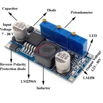
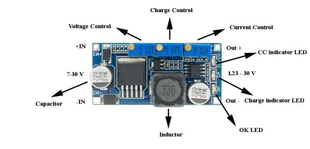
At the input side we have a diode and that diode is marked m4 and the purpose of this diode is that it does not let current come the other way because you can use this to charge a battery. So it will be biased in the positive direction or in the correct direction then we have a 220 micro farad 35 volt capacitor cap on the input which tells me that the maximum input voltage will be 35 volts. But we will keep a margin of safety on that and may be not go higher than 30 volts.
Then we have reverse polarity protection diode which is SS54 that present at the input stage. Now there is chip present on the module which will driving everything this is an LM2596s-adj is an adjustable IC which will be doing most of the stuff. Then we have a 330 micro Henry inductor which is probably going to be part of the buck regulation. Then we have a 78L05IC which is a 5 volt linear regulator and over and at the output stage we have a 35 volt capacitor they probably just used the same capacitor to keep the costs downand then we have an LM358 comparator which is an op-amp or a comparator which seems to be attached to the middle potentiometer and near the LM358 we have LED.
Working of components in the LM2596 module:
The lm2596 buck converter IC, it is also called a switching regulator because it controls the output voltage by switching on and off the output. The input stage, the input range is limited to 7 volts to 30 volts due to the 78l05 used in the module. The rated voltage of the 220 micro farad capacitor at the input terminal is 35 volts which is also a limiting factor for the input voltage.
The output voltage range is 1.23 volts to 30 volts a potentiometer close to the input is intended to control the output voltage turning clockwise increases the output voltage. The potentiometer near the output stage is intended to limit the output current turning clockwise increases the amount of current that can be output. The potentiometer in the middle is a charge control that controls when the charge indicator led goes off turning it clockwise increases the output current level that the ch led turns off in other words the ch led turns off at a higher current. The led close to the out+ port is cc indicator led and it turns on when this lm2596 module is operating in cc mode that is when the maximum current set by current control is being output. The led in the below is a ok led it has an exclusive relationship with the charge indicator led that is when the charge indicator led turns on the ok led turns off.
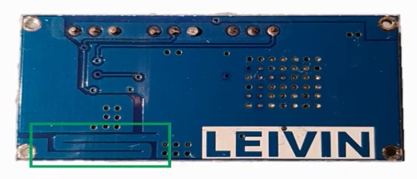
Let’s take a look at the back there seems to be nothing on the back except this maze-like pattern here
This performs the current sensing which is used to limit the output current it is also called trace resistance. All objects have resistance and as the length increases the resistance value increases the larger the cross-sectional area that is the thickness and width the smaller the resistance value by using this characteristic it can be used where a small resistance value is required by measuring the resistance value indirectly approximately 0.026 ohm can be acquired. it is a nice way to save the material cost of one big resistor we have seen in the 2-pot lm2596 module.
Operating Principle of LM2596 Module:
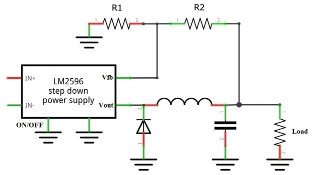
The LM2596 is called a buck converter or it can also be called a step-down converter. The structure of the buck converter is as follows as you can see it operates by turning the switch connected between the input and the output on and off at regular intervals.
Hence it is often called a switching regulator and it is the reason that the output voltage is lower than the input voltage. In order to transfer energy while the switch is turned off storage elements such as inductor and capacitor are required unlike a linear regulator it does not consume heat so the efficiency may be very high up to 90 or more.
The lm2596 adjustable version is capable of supplying 3 ampere of current and the input voltage range is from 4.5 to 40 volts output can be generated from 1.23 volts the internal reference voltage up to 40 volts.
The formula for generating the output voltage is as shown here:
Vout= Vref (1+ R2/R1 )
it is calculated using the resistors connected to the feedback pin of the lm2596 module usually R1 is fixed at a value between 240 to 1.5 kilo ohm and R2 is adjusted to set the output voltage as you can see from the formula the value of R2 has a direct proportionality to the output voltage.
Internal Structure of the LM2596 Module:
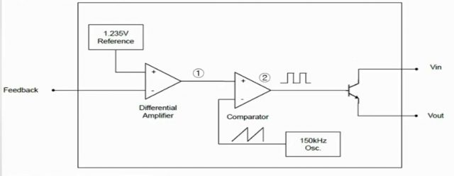
Inside the lm2596 a 1.235 volts reference is generated and supplied to the positive port of the differential amplifier an external feedback pin is connected to the negative port of this differential amplifier.
So when the value of R2 increases the voltage applied to the feedback decreases this will bring a rise in the output of the differential amplifier. Please note that the differential amplifier is an amplifier that amplifies the voltage difference between the positive and negative ports that is the voltage difference between feedback and internal 1.235 volts reference will be amplified by the differential amplifier.
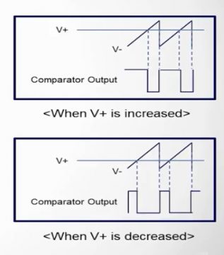
The next stage is a comparator and an oscillator with a frequency of 150 kilohertz is connected to the negative port considering that the comparator output is used to turn on off the transistor it seems reasonable to see it as a sawtooth waveform. The differential amplifier output is connected to the positive pole therefore when the voltage of the positive pole increases the length of the pulse corresponding to high becomes longer and the length of the pulse corresponding to low becomes shorter. In addition when the voltage of the positive pole decreases the length of the pulse corresponding to high becomes shorter and the pulse length corresponding to low becomes longer.
This pulse turns on and off the transistor connected to the output, the longer the high pulse the longer the transistor is on. So the output voltage raises the longer the low pulse the shorter the time the transistor is on so the output voltage will drop. Because of this principle when R2 raises the feedback voltage decreases and the output voltage raises the opposite also applies according to the output voltage through the feedback pin.
Features:
- Input voltage 3.2V ~ 40V
- Output voltage 1.25V ~ 35V
- Output current 3A (max)
- Conversion efficiency of 92% (maximum)
- Output ripple <30mV
- Switching frequency 65KHz
- Operating temperature -45 ℃ ~ +85 ℃
- Size 43mm * 21mm * 14mm (L * W * H)
- IN-IN + input Positive Input Negative
- Positive output OUT + OUT-output negative
Particularly suitable for led driver:
- High power led constant current drive
- Lithium battery charger (including ferroelectric)
- 4V, 6V, 12V, 14V, 24V battery charger
- Nickel cadmium nickel metal hydride battery pack charger
- Solar panels and wind turbines
Applications:
- Step down voltage (buck)
- Dc motor speed control
- Power supply for battery charger
- Light dimmer
- On card switching regulators
- Low power supply application
Buck converter VS Linear Regulator:
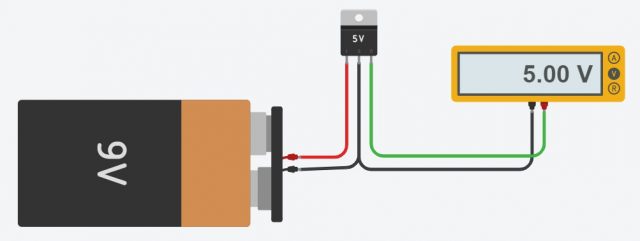
Buck converters great alternative to linear voltage regulators. Linear voltage regulators like LM7805 which is most commonly used. LM7805 are cheap and easy to use.Just supply 9V at the input pin and connect the middle pin of the regulator with the ground. Now connect the multimeter in such way that the positive terminal will be connected at the output and negative terminal will be connected at the ground.
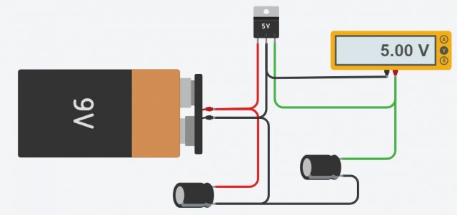
Now in order to remove the ripples we will use capacitor at the input and output. Add a 10uF capacitor on the input, another 10uF capacitor on the output and you get steady 5V.
As we all know, nothing is perfect, and so are linear voltage regulators. They are quite inefficient, because they waste energy and produce a lot of heat. How much heat you may ask?
Let’s take an example If you want to feed your voltage regulator with 9V and draw 500mA on the output, you will have to dissipate 2W of heat.The temperature of your LM7805 will definitely go above 100 degrees C or 212 degrees F.If you want to draw even more current, or
Increase the input voltage you might need a big heat sink,or use a buck converter.Probably all computer power supplies utilize buck converter circuitry to maximize efficiency.You can buy buck converters in different shapes, sizes, and with different specifications. Another name for a buck converter is voltage step down converter, which describes its purpose pretty well. In buck converter we will apply the voltage at the input and you get constant lower voltage at the output.
The output voltage is adjusted by this potentiometer.For example, you can set it to 5V and this becomes a very efficient 5V voltage regulator.Let’s compare in practice LM7805 linear voltage regulator with this really small buck converter. Both are given 12V on the input and they provide 5V on the output.The driver boards from these old hard drives consume approximately 450mA and they will serve as my dummy load.
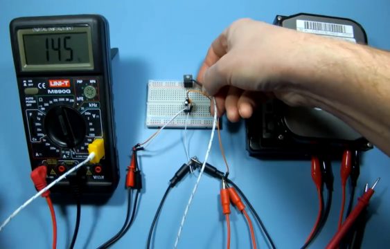
I will measure the power consumption and temperature of the linear voltage regulator and the buck converter under the same load 15 minutes after powering up. Only 2 minutes later the LM7805 consumes about 420mA at 12V, but as you can see the power consumption drops to 0 and then goes back to 420mA over and over again.The LM7805 shuts down if the temperature goes too high. It can operate properly up to 125 degrees C or 257 degrees F.Then let’s check the temperature. As you can see it’s well above the safe range,so the regulator shuts downand turns on after cooling down a bit.
The linear voltage regulator draws 420mA at 12V, which gives us 5.04W.
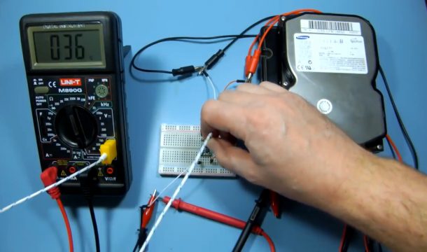
Now let’s check if the buck converter can finish the same test. After exactly15 minutes the buck converter draws the only 220mA at 12V, which is only 2.64W.In this configuration, the linear voltage regulator consumes over 90% more power than the buck converter, which is worth considering, especially when your device is battery powered.Now, let’s check the temperature. As you can see, the buck converter stays at only 38 degrees C or 100 degrees F.
In this example the superiority of the buck converter is very clear, but you can buy an LM7805 for about 30 cents, while the cheapest buck converter will cost you about $2.5.There is one more thing – because buck converters use coils, they may cause interference in your circuits, so if you are building something sensitive, like a radio, for example, you should grab a linear voltage regulator and live with all its drawbacks. On the other hand, when you are designing a device in a small enclosure, where proper airflow cannot be provided, a linear voltage regulator with a big and hot heat sink is probably not a good idea. Now you know the main advantages and disadvantages of buck converters and linear voltage regulators.
