Proximity Sensors: Inductive and Capacitive Proximity Sensors with Arduino
Table of Contents
Proximity sensors:
Proximity actually meaning is nearness, so the proximity sensor is a sensor able to detect the presence of nearby objects by generating frequency without any contact with the object. Electromagnetic radiation is emitted by proximity sensor for instance and looks for changes in the field or return signal. The object being sensed is often referred to as proximity sensors target depending on the proximity sensor target.
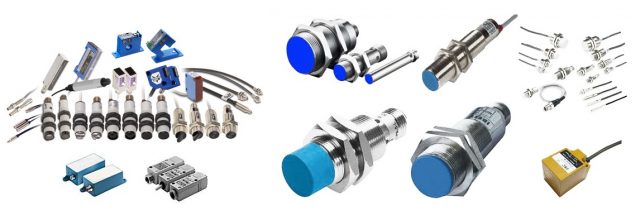
Proximity sensor has a long functional life and can be available in various shapes and materials such as plastic, metallic or having circular and rectangular shape. Some proximity sensors are the combination of metallic and plastic. The proximity sensor has high reliability due to the absence of mechanical parts and the lack of physical contacts between sensor and the target. A proximity sensor that is adjusted to very short range can often be used as touch switch. Proximity sensors are commonly used in industrial application from manufacturing and food production to recycling. They are also used in vehicles for detecting the proximity of other vehicles relative to one own car as well as for parking such as how many cars enter to the parking area, assist function in mobile devices especially phones. The proximity sensor is used to detect whether a user face is close to the phone during a phone call from opening the screen to turn off to prevent false touches on the touch screen.
Types of Proximity Sensors:
Inductive Proximity Sensor
Capacitive Proximity Sensor
Optical Proximity Sensor
Magnetic Proximity Sensor
Ultrasonic Proximity Sensor
Amazon Purchase Links:
Arduino Nano USB-C Type (Recommended)
Other Tools and Components:
ESP32 WiFi + Bluetooth Module (Recommended)
Super Starter kit for Beginners
PCB small portable drill machines
*Please Note: These are affiliate links. I may make a commission if you buy the components through these links. I would appreciate your support in this way!
Inductive proximity sensors:
Inductive sensors can be available in both ac and dc supply operated. Some inductive sensor consists of 2 wires while some consists of three to four wires. It can be available in various shapes such as tubular, rectangular and ring shaped. Inductive sensor can detect a target from 0.5 millimeters to 40 millimeters. They only detect metallic targets and therefore use a magnetic field to its presence. The inductive sensor consists of sensing coil which is ferromagnetic coil having copper turns.
The working principle of the inductive proximity sensor is based on the electromagnetic induction. The coil will generate high frequency oscillation field. Electrical currents known as eddy currents are induced on the metal surface when a ferrous metal material enters the magnetic field. These eddy current induce power loss within the oscillator circuit and in turned caused a reduction in the amplitude of the oscillations this is known as echo or eddy currents kill oscillator principle. This change in amplitude sends a signal to the switch changing it to its normally open or normally closed configuration respectively. When the metal target is removed from the proximity inductive sensor range the oscillator will return to its normal state and the switch will return to its normally closed or open output. An inductive proximity sensor consists of three wires brown, black and blue. In which brown wire is connected with the positive terminal of the dc supply, blue will be connected with the dc GND and black wire is the signal output. Its voltage range is from 5 to 32V.
Due to such a wide input voltage range, we can use this inductive proximity sensor with PLCs and 5V compatible controller boards like Arduino Uno, Arduino Mega, Arduino Nano, PIC, etc. You can also use these inductive proximity sensors without programmable controller.
Types of Inductive Proximity Sensors NPN and PNP:
The inductive proximity sensors are available in two different types NPN and PNP. Both types are used for the same purpose; the only difference is in the wiring. The PNP type inductive proximity sensor will give positive voltage as the output, while the NPN type inductive sensor will give GND or 0 as the output signal. So, basically PNP type inductive proximity sensor is opposite of the NPN type proximity sensor.
We have 24V dc supply, a proximity sensor auxiliary contactor. We will connect the brown wire of the sensor with the positive terminal of the battery and blue wire with the negative terminal of the battery. Black wire of the sensor which is signal wire is connected with the A1 terminal of the contactor the other point A2 of the contactor will be connected with the dc common. Whenever the sensor output will be on then auxiliary contactor will be on.
Output of the NPN and PNP type Inductive proximity Sensor:
The NPN type sensor will give you 0 or GND as the output signal. While for the PNP type Inductive proximity sensor, you know the type of inductive sensor I am talking about can be powered up using 5-32Vdc. So if the sensor is powered up using the 5v then the sensor output will be 5v, if the sensor is powered up using 12v, then the sensor output will be 12v, and so on. To make this clear and easy to understand, let’s use this inductive sensor with the Arduino.
Inductive sensor with Arduino:
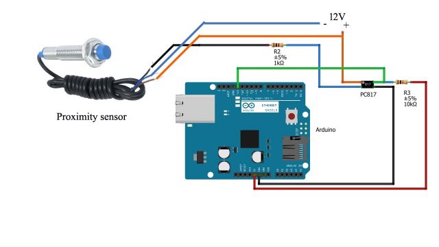
Connect 1KΩ resistor with pin number 2 of the PC817 and connect other terminal of the resistor with the black wire of the sensor. Connect pin number 4 of the PC817 with the 10KΩ resistor and connect other terminal of the resistor with 5V of the Arduino. Connect pin number 3 of the PC817 with the ground terminal of the Arduino. Connect pin number 1 of the PC817 with the 12 V power supply. Connect the brown wire of the sensor with the +12V. Connect the blue wire with the ground terminal. Connect pin number 4 of the PC817 with Arduino pin number 13.
Inductive Proximity Sensor Arduino Code:
|
1 2 3 4 5 6 7 8 9 10 11 12 13 14 15 16 17 18 19 20 21 22 23 24 25 26 |
int limitswitch=13; int state= LOW; int value; void setup() { Serial.begin(9600); pinMode(limitswitch,INPUT); } void loop() { Value = digitalRead(limitswitch); if(value!=state) { state=value; Serial.println("sensor value ="); if (state==0) { Serial.println("target detected"); } else{ Serial.println("No target detected"); } } } |
DC motor control through Inductive proximity sensor and Arduino:
Component required:
- Arduino UNO
- Proximity sensor
- 5V relay
- DC motor
When the proximity sensor detects or observes some obstacles in front of it 5V relay NC will be generated and react as a switch to activate the motor and make it rotate the fan to produce some wind.
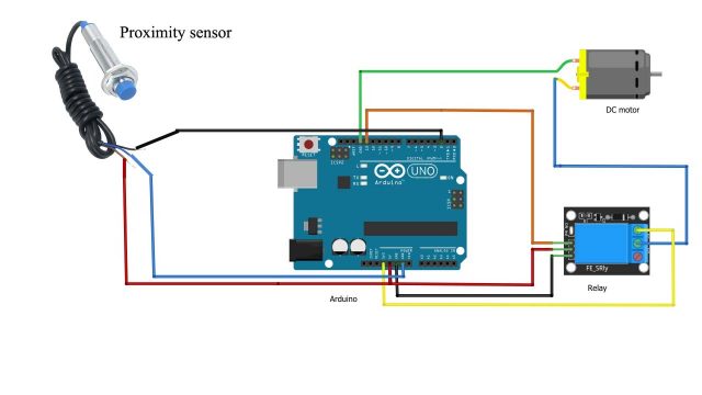
In this project we will control dc motor with proximity sensor. Connect one wire of the dc motor with the common of the relay. Connect other wire of the motor with the ground of the Arduino. Connect the normally close contact of the relay with the 3.3V. Connect the input of the relay with pin number 13 of the Arduino. Connect the ground of the relay module with the ground of the Arduino. Connect VCC of the relay module with the 5V of the Arduino. Connect the black wire of the proximity sensor with the digital pin number 2. Connect brown wire of the proximity sensor with the VCC. Connect blue wire of the sensor with the ground of the Arduino.
DC Motor and Inductive Proximity Sensor Arduino Code:
|
1 2 3 4 5 6 7 8 9 10 11 12 13 14 15 16 17 18 19 20 21 22 23 24 |
int motor=13; // int inpin=2; // proximity sensor connected with the pin 2 int val=0; // this variable will read the value from the sensor void setup() { pinMode(motor,OUTPUT); pinMode(inpin,INPUT); } void loop() { val=digitalRead(inpin); if(val==HIGH) { digitalWrite(motor,LOW); delay(5000); } else { digitalWrite(motor,HIGH); delay(5000); } } |
2 wire AC inductive proximity sensor:
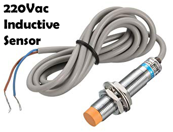
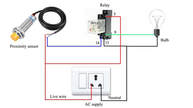
This type of sensor is mostly used in industries. We have to remember two things while using this type of sensor. First thing to remember is that this sensor work on 220V AC while the second thing to remember is that we will use this sensor in series with the load when the sensor will detect the target sensor will give signal and the load will be operated.
This sensor consists of two wires brown and blue. When we will connect the live wire with black or brown wire of the sensor. So, when a target is detected we will get 220V on the other end of the sensor. Suppose we have connected the live wire with the brown wire of the sensor then we get 220V at the black wire of the sensor when target will come in front of the sensor. If we want to operate maximum load we will use relay. We does not connect the appliance directly with the sensor because the appliance will draw more current which will flow in the circuit it may damage the sensor. So we will use relay to prevent the sensor from any damage. Depending upon the load we will use relay if our load is 5A we will use 5A relay better if we use slight a relay that has the rating greater than 5A. The range of this sensor is 8mm and the voltage require for this sensor is 220V.
220Vac Inductive Proximity Sensor with Relay:
Connect the brown wire with the live wire and blue wire with the relay. The point 13 and 14 are the supply point of the relay. Connect the blue wire with the point 14. Connect the pin 13 of the relay with the neutral. Connect one end of the light with the neutral wire and other end with the relay pin number 9. Now the circuit connections are completed so when the target will come in front of the sensor the relay will operate. The sensor back light will be turn on and off when a target comes in front of it.
Capacitive Proximity sensors:
Capacitive proximity sensors on the other hand can detect dielectric materials such as liquid, plastic, glass, wood and granulated substances as long as it has a dielectric constant of 1.2 or more. Capacitive sensor can detect metallic and non-metallic objects material. Sensing range can depend on the material needed to be detected their range is from 2 millimeters to 15 millimeters depending on the dielectric material to be detected. There is no de-rating factor to be applied when sensing metal targets but other materials do affect sensing range. Generally the sensing distance for proximity capacitive sensor is greater for larger or denser targets, but the effect on electrostatic field produced by the non-conductive material can be quite small. Usually sensing distances with this material is short. Two small plates located in the front of sensor form a capacitor as a target enter the sensors range the capacitance of the two plate’s increases thus causing a change in the oscillator frequency which also activates the sensor output either normally open or normally closed respectively.
Capacitive sensor can detects any target that has a dielectric constant greater than air. The dielectric constant is an electrostatic field generated by the oscillator circuit. If an object enters this field and causes interference, oscillation than begins. The oscillator output is monitored by detector or trigger circuit. When it detects the sufficient change in the field, it switches on the output circuit. The output circuit remains active when the target is in front of the sensor, the sensor will be active and the sensor will be in off state when the target is removed from the sensing field. Sensors can be used to detect liquid through a non-metallic material such as glass or plastic but they need to be mounted so that the sensor detects just the liquid and not the container.
Material such as un-grounded material can be sensed from further away because it causes more interference on the electrostatic field. Grounded conducted material causes even more interference and thus has the longest sensing distance. Since the composition of the material and ambient condition have impact on the sensing field. Many proximity capacitive sensors are equipped with sensitivity adjustment potentiometer. Capacitive proximity switches can detect materials at greater ranges from inductive sensors and have long operation life.
Applications:
- Liquid level detection
- Material level control
- Counting
- Induction molding process such as detection level of plastic pellets
Let’s use a capacitive Touch sensor with the Arduino.
Capacitive Touch Sensor with Arduino:
Capacitive Touch Sensor with Arduino Code:
|
1 2 3 4 5 6 7 8 9 10 11 12 13 14 15 16 17 18 19 20 |
#define C_Touch_Sensor 1 // The capactitive touch sensor is connected to Arduino Digital pin D1 int ledPin = 13; // Output display LED void setup() { Serial.begin(9600); // Baud rate pinMode(ledPin, OUTPUT); pinMode(C_Touch_Sensor, INPUT); } void loop() { int C_Value = digitalRead(C_Touch_Sensor); if (C_Value == HIGH){ digitalWrite(ledPin, HIGH); Serial.println("Touch detected"); } else{ digitalWrite(ledPin,LOW); Serial.println("no touch"); } delay(200); } |
Photoelectric proximity sensors:
Photoelectric sensor use light sensitive element to detect objects. Photoelectric proximity sensor may be ac or dc which uses direct reflection. In Photoelectric distance can be adjustable. Photoelectric sensor has greatest detection range from one millimeter to 25 meters or more. They operate by the use of an emitter which transmits a beam of the light to the receiver. When the light is normally being received it is known as dark operated mode. The sensor is said to be in light operated mode when the absence of light is required.
In this dark operated mode, let’s for example a laser is installed on one side of the garage door while the light sensor is installed on the other side. In normal condition the light falls on the light sensor. So, when anyone crosses the laser light, the light will no long fall on the sensor, this will signal the controller to open the garage door. The same also applies to the Laser trip wire security system.
Conversely in this light operated mode example the absence of light being received by the receiver is normal. When the object is removed from the table the switch is triggered and alarm will sound.
Let me explain this in a more practical way. The following is the circuit diagram of the day and night detection system which controls a light automatically.
This is quite a versatile circuit, you can use it with lasers, you can use it to detect light in rooms, can be used to detect sunlight, and so on.
IR Proximity Sensor:
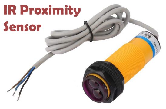
This is the IR proximity sensor which is one of the most commonly used sensors in the industries. These IR proximity sensors are used for the object detection. Starting with the wires of the IR Proximity Sensor. Unlike the Inductive sensor the IR proximity sensor also has 3 wires “Brown, Blue, and black”. Brown is the +V, Blue is the GND, and Black is the output signal wire.
On the front, this IR proximity sensor is provided with two IR LEDs. One is the transmitter and the other one is the receiver. One an object comes in front of the IR proximity sensor, the light is reflected by the object and when received by the Rx Led a signal is generated. This sensor also has an LED which lights up each time an object is detected.
The IR proximity sensor also has the PNP and NPN types. The IR proximity sensor can be used just like the inductive proximity sensor.
Proximity sensors applications:
Proximity sensors have high long functional life and high reliability due to the absence of mechanical parts and the lack of physical contact between the sensor and a target. A proximity sensor that is adjusted to a very
- Inductive proximity sensors are used in elevators.
- Capacitive proximity sensors are used to detect liquids and other dielectric materials on the manufacturing floors.
- Photoelectric sensors are used in our homes and countless other applications.
Related Projects:
Capacitive Soil Moisture Sensor:
IR Proximity Sensor with PLC for Bidirectional counting:






Hi, thanks for your information. I find it really helpful. However, I was wondering. If I were to use the inductive proximity sensor with pneumatic solenoid valve, will it has the same wiring configurations as the one in your post regarding the DC motor control through Inductive proximity sensor and Arduino?