Capacitive Soil Moisture Sensor Arduino Circuit diagram and programming
Last Updated on August 17, 2024 by Engr. Shahzada Fahad
Table of Contents
Description:
Capacitive Soil Moisture Sensor Arduino– In this tutorial, you will learn how to use the Capacitive Soil Moisture Sensor v1.2 with Arduino and display the Soil Moisture value on a 16×2 i2c LCD module. The soil moisture is monitored in real-time. A 12volt dc water pump is controlled as the soil moisture increases or decreases below a certain pre-defined value.
I have been using soil moisture sensors with Arduino Uno and Nodemcu ESP8266 Wifi module for monitoring the soil moisture in real-time from anywhere around the world. In my previous tutorials, I used Resistive type soil moisture sensors which were not durable.
The Resistive type soil moisture sensors are easily subjected to corrosion. While on the other hand the capacitive soil moisture sensor is made up of the corrosion resistant material. I will cover more technical things about the capacitive soil moisture sensor in a minute. Read my articles on Arduino-based Hydroponics System and Arduino-based NPK Sensor for Soil Nutrients Monitoring.
In this tutorial, we will cover
- Capacitive soil moisture sensor technical specification
- Capacitive soil moisture sensor interfacing with Arduino
- Complete circuit diagram explanation
- Capacitive soil moisture sensor Arduino Programming
Without any further delay let’s get started!!!
Amazon Links:
Arduino Nano USB-C Type (Recommended)
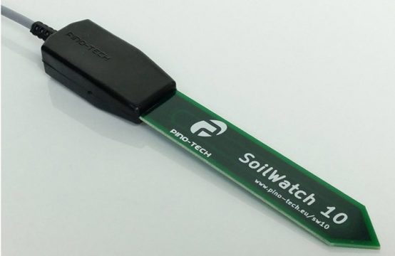
Capacitive Soil Moisture Sensor V1.2:
*Disclosure: These are affiliate links. As an Amazon Associate I earn from qualifying purchases.
About the Capacitive soil moisture sensor V1.2:
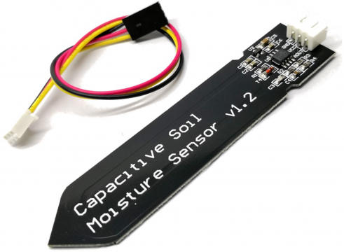
This is a soil moisture sensor that measures soil moisture levels by capacitive sensing rather than resistive sensing like other sensors on the market. As I said earlier this capacitive sensor by the DFROBOT is made of corrosion-resistant material which gives it excellent service life.
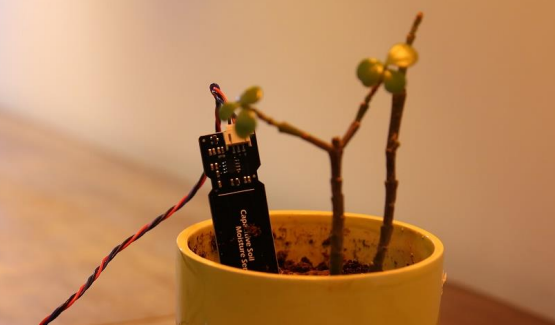
The capacitive soil moisture sensor is used just like the Resistive soil moisture simply insert it in to the soil around your plants and make an amazing low cost real time soil moisture monitoring system.
This module includes an on-board voltage regulator which gives it an operating voltage range of 3.3 to 5.5V. It is perfect for low-voltage MCUs, both 3.3V and 5V.
Capacitive Soil Moisture Specification:
Operating Voltage: 3.3 ~ 5.5 VDC
Output Voltage: 1.2 ~ 2.5V
Interface: PH2.0-3P
Dimension: 98mm * 23mm (3.86in x 0.905in)
Weight: 15g
FEATURES
Supports Gravity 3-Pin Interface
Analog Output
APPLICATIONS
Gardening & Farming
Moisture Detection
Intelligent Agriculture
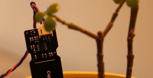
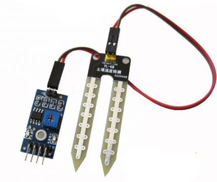
This white line is the warning line, which means don’t insert this into the soil or the sensor will be damaged. Some Capacitive soil moisture sensors available in the market does not have this warning line; so no matter if the line is present or not don’t insert this sensor completely into the soil. There are some types of the soil moisture sensors in which the electronic components are completely sealed. Like the one you can see in the picture below.
But I am using a capacitive soil moisture sensor by the DFrobot, so I will stick to it.
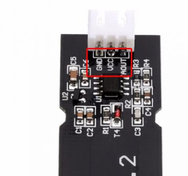
This soil moisture sensor is provided with a connector which is clearly labeled as GND, VCC, and AOUT. The GND and VCC are the power pins and these should be connected with the Arduino’s GND and 5V. While the AOUT is the analog output pin which can be connected to any analog pin of the Arduino board.
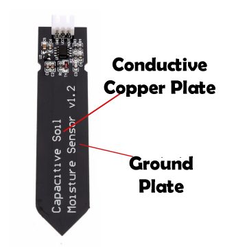
The Capacitive soil moisture sensor has one conductive copper plate in the center and then a ground plate that goes around the outside.
One more thing that I would like to share with you guys which will further increase the life span of this capacitive soil moisture sensor is that if you look closely at the edges of the soil moisture sensor; you will find these edges exposed.
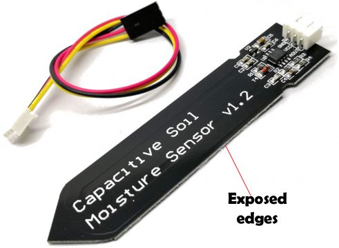
In the long term use this will lead to the corrosion and can badly effect the measurement. You can make this corrosion resistant by applying some kind of glue or any other material which can cover the exposed edges of the capacitive soil moisture sensor.
Capacitive Soil Moisture Sensor Working Principle:
A capacitive moisture sensor works by measuring the changes in capacitance caused by the changes in the dielectric. It does not measure moisture directly (pure water does not conduct electricity well), instead it measures the ions that are dissolved in the moisture These ions and their concentration can be affected by a number of factors, for example adding fertilizer for instance will decrease the resistance of the soil. Capacitive measuring basically measures the dielectric that is formed by the soil and the water is the most important factor that affects the dielectric.
Capacitive measuring has some advantages; it not only avoids corrosion of the probe but also gives a better reading of the moisture content of the soil as opposed to using a resistive soil moisture sensor. Since the contacts (the plus plate and the minus plate of the capacitor) are not exposed to the soil, there is no corrosion of the sensor itself.
The capacitance of the sensor is measured by means of a 555 timer based circuit that produces a voltage which is proportional to the capacitor inserted in the soil. We then measure this voltage by use of an analog to digital converter which produces a number that we can then interpret as soil moisture.
Soil Moisture Sensor Circuit Diagram:
I2c 16×2 LCD, 12Vdc water pump, and capacitive soil moisture sensor interfacing with Arduino Uno.
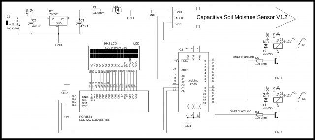
Let’s start with the i2c 16×2 LCD. As you can see the circuit diagram is really simple. All the 16 pins of the PCF8574 driver module are connected with the LCD pins. Using these connections you can convert any 16×2 LCD into an i2c supported LCD. The VCC pin is connected with the Arduino’s 5 volts, the SDA pin is connected with the Arduino’s Analog pin A4, the SCL pin is connected with the Arduino’s Analog pin A5, while the GND pin is connected with the Arduino’s ground. Using only two pins A4 and A5 we can control the 16×2 LCD.
The circuit given at the top left corner is the regulated power supply based on the LM7805 voltage regulator. This regulated power supply is optional but it is good if you make this power supply, if in case later you decide to add more electronic components, then you can use this power supply for powering up the components this way the Arduino board will not be overloaded.
The capacitive soil moisture sensor interfacing with Arduino is very simple and I don’t think so I need to explain this.
On the right side you can see there is a two channel relay module. A relay connected with the Arduino’s pin number 12 is used to control the Water pump while the relay connected with the Arduino’s pin number 13 is used to control the Buzzer. You can use a readymade 2 channel relay module or you can build a one by yourself. Let me explain how you can make a relay module.
For controlling these relays we will need relay drivers, the relay drivers simply consists of the 2n2222 NPN transistors, 10k ohm resistors and diodes. As you can see a 10k resistor is connected with the base of 2n2222 NPN transistor as it’s a BJT “bipolar junction transistor” a current controlled device, that’s why we need a current limiting resistor. We usually use a 10k resistor. The emitter of the 2n2222 NPN transistor is connected with the ground while the collector is connected with one side of the relay coil, while the other side of the relay coil is connected with 12v. This relay can be energized and de-energized using this transistor.
As you can see this relay consists of 5 pins, two coil pins, common, normally closed and normally open. These three pins have no physical connection with the coil pins. All the connections are exactly the same. These are freewheeling diodes, used against back EMF protection.
You might be thinking how we know we have to use the 2n2222 NPN transistor? Or can we use any other NPN transistor?
These are the kind of questions which every beginner ask. It is very simple. The relay coil has a resistance which you can measure using a digital multimeter. Once you find the resistance then you can use the Ohm’s law V = IR and you can easily calculate the current needed to energize the relay coil.
The type of the relays used in this project are 12V. So
V = 12V
R = .394K ohm
We can calculate the current.
I = V/R
And we get
I = 30ma
So, now we know that we need at least 30ma to energize the relay coil. Now you can use any general purpose NPN transistor whose collector current is greater than 30ma. I selected 2n2222 NPN transistor, these are cheap, easily available, and has collector current rating more than 700ma, it’s amazing.

I tested my relay driver in a Proteus simulation and it worked perfectly. Now, let’s have a look at the Arduino programming.
Capacitive soil moisture sensor V1.2 Arduino Code / Programming:
Download Arduino libraries
|
1 2 3 4 5 6 7 8 9 10 11 12 13 14 15 16 17 18 19 20 21 22 23 24 25 26 27 28 29 30 31 32 33 34 35 36 37 38 39 40 41 42 43 44 45 46 47 48 49 50 51 52 53 54 55 56 57 58 59 60 61 62 63 64 |
/* Capacitive soil moisture Arduino programming www.electroniclinic.com Download Arduino libraries: */ #include <Wire.h> #include <LiquidCrystal_I2C.h> LiquidCrystal_I2C lcd(0x27,16,2); //0x27 is the i2c address, while 16 = columns, and 2 = rows. int msensor = A1; // moisture sensor is connected with the analog pin A1 of the Arduino int msvalue = 0; // moisture sensor value long int data; int relay1 = 13; // to control the Buzzer int relay2 = 12; // to control the motor or anything else int sdata1 = 0; // Moisture sensor value void setup() { Serial.begin(9600); lcd.init(); //Init the LCD lcd.backlight(); //Activate backlight lcd.home(); pinMode(msensor, INPUT); pinMode(relay1, OUTPUT); pinMode(relay2, OUTPUT); digitalWrite(relay1, LOW); digitalWrite(relay2, LOW); } void loop() { msvalue = analogRead(msensor); Serial.println(msvalue); delay(1000); lcd.clear(); lcd.print("Soil Moisture:"); lcd.setCursor(0,1); lcd.print(msvalue); if (msvalue > 400) { digitalWrite(relay1, HIGH); digitalWrite(relay2, HIGH); delay(500); } if (msvalue < 400) { digitalWrite(relay1, LOW); digitalWrite(relay2, LOW); delay(500); } } |
Capacitive soil moisture sensor Arduino code explanation:
Before you start the programming first of all, make sure that you download the necessary libraries needed for this project. the libraries download link is already given above.
#include <Wire.h>
#include <LiquidCrystal_I2C.h>
LiquidCrystal_I2C lcd(0x27,16,2); //0x27 is the i2c address, while 16 = columns, and 2 = rows.
The capacitive soil moisture sensor is connected with the Analog pin A1.
int msensor = A1; // moisture sensor is connected with the analog pin A1 of the Arduino
int msvalue = 0; // moisture sensor value
long int data;
the two relays are connected with the Arduino pins 13 and 12.
int relay1 = 13; // to control the Buzzer
int relay2 = 12; // to control the motor or anything else
int sdata1 = 0; // Moisture sensor value
void setup()
{
Serial.begin(9600); // activates the Serial communication, 9600 is the baud rate.
lcd.init(); //Init the LCD
lcd.backlight(); //Activate backlight
lcd.home();
The capacitive soil moisture is set as the input using the pinMode() function.
pinMode(msensor, INPUT);
The relays are set as the output.
pinMode(relay1, OUTPUT);
pinMode(relay2, OUTPUT);
By default keep the relays OFF.
digitalWrite(relay1, LOW);
digitalWrite(relay2, LOW);
}
void loop()
{
First we read the capacitive soil moisture sensor using the analogRead() function and the value is stored in the variable msvalue.
msvalue = analogRead(msensor);
Serial.println(msvalue);
delay(1000);
first we clear the LCD.
lcd.clear();
print a message on the LCD.
lcd.print(“Soil Moisture:”);
lcd.setCursor(0,1);
lcd.print(msvalue);
Using the if conditions we control the relays. 400 is the predefined value which can be selected as per the requirement.
if (msvalue > 400)
{
digitalWrite(relay1, HIGH);
digitalWrite(relay2, HIGH);
delay(500);
}
if (msvalue < 400)
{
digitalWrite(relay1, LOW);
digitalWrite(relay2, LOW);
delay(500);
}
}
Watch Video Tutorial:
Related Project:
Arduino Soil Moisture Sensor Getting Started Tutorial:
Arduino IOT Project: watering plants and soil moisture monitoring:
Discover more from Electronic Clinic
Subscribe to get the latest posts sent to your email.


When I try to compile your sketch, “Capacitive soil moisture Arduino programming”, I get the error, “exit status 1
‘int LiquidCrystal_I2C::init()’ is private within this context”
Why?
What must I do the correct it?