Serial communication between two Arduino boards
Last Updated on August 17, 2024 by Engr. Shahzada Fahad
Table of Contents
Description:
Serial communication between two Arduino boards- In this tutorial, you will learn how to perform the Serial Communication between two Arduino boards. Although for most of the projects Arduino Uno or Arduino Mega is more than enough to design advanced level projects like CNC machines, 3D Printers, etc. There are times when the single Arduino Uno or Arduino Mega, or any other Arduino board is not enough to complete the project, then in a situation like this you can Serial connect multiple Arduino boards. After reading this article, you will be able how to use the Serial.read() and Serial.wrtie() functions. I will start with the very basics and after you learn the basic concept of Serial communication, then I will take it to the next level and we will do some advanced level things.
In this article I will also explain how to perform the Serial communication between Arduino Uno and Arduino Mega. Apart from the Serial communication between two Arduino boards you can also use the same concept in performing serial communication with all other serial supported devices like example,
Arduino Serial Communication with Nodemcu ESP8266
Arduino Serial Communication with Lora by Reyax technologies
Arduino Serial Communication with Vb.net
Arduino Serial Communication with 10.1” HMI LCD
Arduino Serial Communication with the Voice Recognition Module
Serial communication between Lora and ESP8266
Arduino Serial Communication with GSM Module
Arduino Serial Communication with GPS Neo 6M Module
Arduino Serial Communication with Multiple Devices
Above are some of the intermediate and advanced level projects based on the one way and two way Serial Communication systems. For the beginners these tutorials are hard to follow. So that’s why I decided to write an easy to follow tutorial on the Serial Communication between two Arduino boards. Without any further delay, let’s get started!!!
Amazon Purchase Links:
Arduino Nano USB-C Type (Recommended)
*Disclosure: These are affiliate links. As an Amazon Associate I earn from qualifying purchases.
How to serially connect two Arduino Boards?
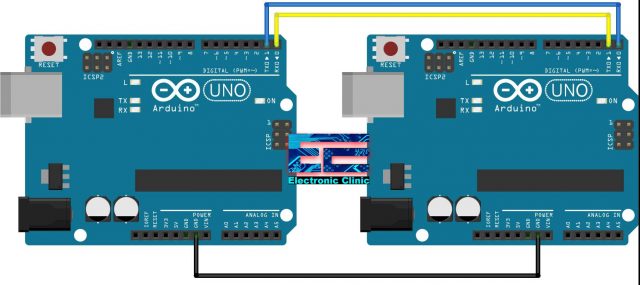
You will only need three male to male type jumper wires to get started with the two Arduino Boards. The RX of one Arduino Uno board is connected with the TX pin of the other Arduino board and similarly the TX pin is connected with the RX pin of the other Arduino board. Tx to Rx and Rx to Tx. Make sure the grounds of both the Arduino boards are connected together.
Serial Communication between Two Arduino Boards, Programming:
Now, to understand the concept of the serial communication between two Arduino boards, let’s use one Arduino board as the Sender and the other Arduino board as the receiver. This means we will need to write two programs, one for the Sender Arduino and the other for the Receiver Arduino.
Sender Arduino Code:
|
1 2 3 4 5 6 7 8 9 10 11 12 13 14 15 16 17 18 19 20 |
char Mymessage[5] = "Hello"; //String data void setup() { // Begin the Serial at 9600 Baud Serial.begin(9600); } void loop() { Serial.write(Mymessage,5); //Write the serial data delay(1000); } |
Sender Arduino code Explanation:
This is the simplest code. The purpose of this program is to send the message Hello to the other Arduino board. I defined an array Mymessage. The number 5 inside the brackets shows that this array can hold 5 characters. Inside the setup(), I activated the serial communication using the Serial.begin() function and selected 9600 as the baud rate. The setup() function executes only one time when the Arduino board is first turned ON.
The loop() function executes again and again until you turn OFF the Arduino board. To Send the Hello message to the receiver Arduino board we use the Serial.write() function and then there is a delay of 1000 milliseconds which is equal to 1 second.
Receiver Arduino Code:
|
1 2 3 4 5 6 7 8 9 10 11 12 |
char Mymessage[10]; //Initialized variable to store recieved data void setup() { // Begin the Serial at 9600 Baud Serial.begin(9600); } void loop() { Serial.readBytes(Mymessage,5); //Read the serial data and store in var Serial.println(Mymessage); //Print data on Serial Monitor delay(1000); } |
Receiver Arduino Code Explanation:
The code of the Receiver Arduino is almost similar to that of the Sender Arduino. But this time instead using the Serial.write() function we use the Serial.readBytes() function to read the data.
Now, you can upload the codes, open the Serial monitor for the Receiver Arduino. Make sure the Sender Arduino is powered up using a cable, adaptor, or you can even use the Receiver Arduino to power up the Sender Arduino, for this you will need to connect 5volts from the Receiver Arduino with the Vin pin of the Sensor Arduino.
Now you can connect a variable resistor with the Sender Arduino and try to send its value to the receiver Arduino and then print on the Serial monitor.
Note: if you get an error while uploading the program, remove the wires from the tx and rx pins. Again upload the code, and also make sure the right Arduino boards are selected.
Arduino Uno Serial Communication with Arduino Mega:
Now, let’s take this to another level, this time we will control an LED. We will send commands “on” and “off” from the Arduino Mega to the Arduino Uno using Serial communication to control the onboard LED connected with the Arduino Uno pin number 13. So in this example Arduino Mega will be used as the Sender and the Arduino Uno will be used as the receiver.
Arduino Uno Serial connection with Arduino Mega, Circuit Diagram:
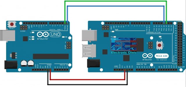
The RX1 of the Arduino Mega is connected with the TX0 of the Arduino Uno. The TX1 of the Arduino Mega is connected with the RX0 of the Arduino Uno. The 5v from the Arduino Mega is connected with the Vin pin of the Arduino Uno. This time we will power up the Arduino Uno using the Arduino Mega’s 5 volts. Make sure, the grounds of both the Arduino boards are connected together. My recommendation is do the wiring after you upload the codes.
Arduino Mega Code, Sender:
|
1 2 3 4 5 6 7 8 9 10 11 12 13 14 15 16 17 18 19 20 21 22 23 24 25 26 27 28 29 30 31 32 33 34 35 36 37 38 39 40 41 42 43 44 45 46 47 48 49 50 51 52 53 |
void setup() { // put your setup code here, to run once: Serial.begin(9600); Serial1.begin(9600); } void loop() { // put your main code here, to run repeatedly: String readString; String Q; //-------------------------------Check Serial Port--------------------------------------- while (Serial1.available()){ delay(1); if(Serial1.available()>0){ char c = Serial1.read(); Serial.print(c); if (isControl(c)){ break; } } } while (Serial.available()) { delay(1); if (Serial.available() >0) { char c = Serial.read(); //gets one byte from serial buffer if (isControl(c)) { //'Serial.println("it's a control character"); break; } readString += c; //makes the string readString } } Q = readString; //--------Checking Serial Read---------- if(Q=="on"){ Serial1.print("1"); Serial.println("Sent:On"); } if(Q=="off"){ Serial1.print("2"); Serial.println("Sent:Off"); } } |
Arduino Mega, Sender code explanation:
Inside the setup() function you can see I have activated two Serial Ports on the Arduino Mega. For both the Serial Ports I selected 9600 as the baud rate. One serial port is used for entering the command and the other serial port is used for sending the command to the Receiver.
void setup() {
// put your setup code here, to run once:
Serial.begin(9600);
Serial1.begin(9600);
}
void loop() {
I started by defining a variable readString of the type String and I also defined another variable Q of the type String.
String readString;
String Q;
//——————————-Check Serial1 Port—————————————
The following set of instructions is used to check if data is available on the Serial1 port, if data is available then read the Serial1 port and store it in
while (Serial1.available()){
delay(1);
if(Serial1.available()>0){
char c = Serial1.read();
Serial.print(c);
if (isControl(c)){
break;
}
}
}
The following set of instruction monitors the Serial0 port, you can call this as the default Serial port. This port receives the data when we write a command on the serial monitor. all the characters that we type are added with the variable readString to complete a message.
while (Serial.available()) {
delay(1);
if (Serial.available() >0) {
char c = Serial.read(); //gets one byte from serial buffer
if (isControl(c)) {
//’Serial.println(“it’s a control character”);
break;
}
readString += c; //makes the string readString
}
}
This message is then stored in the variable Q.
Q = readString;
Then using the if conditions we check if the variable Q consists of “on” or “off” and then send 1 or 2 accordingly.
//——–Checking Serial Read———-
if(Q==”on”){
Serial1.print(“1”);
Serial.println(“Sent:On”);
}
if(Q==”off”){
Serial1.print(“2”);
Serial.println(“Sent:Off”);
}
}
So, Serial1 port is used for sending the data from the Arduino Mega to the Arduino Uno, while the Serial0 port is used for entering the commands through the Serial Monitor.
Arduino Uno Code, Receiver:
|
1 2 3 4 5 6 7 8 9 10 11 12 13 14 15 16 17 18 19 20 21 22 23 24 25 26 27 28 29 30 31 32 33 34 35 36 37 |
void setup() { // put your setup code here, to run once: pinMode(13,OUTPUT); Serial.begin(9600); } void loop() { // put your main code here, to run repeatedly: String readString; String Q; //-------------------------------Check Serial Port--------------------------------------- while (Serial.available()) { delay(1); if (Serial.available() >0) { char c = Serial.read(); //gets one byte from serial buffer if (isControl(c)) { //'Serial.println("it's a control character"); break; } readString += c; //makes the string readString } } Q = readString; //--------Checking Serial Read---------- if(Q=="1"){ digitalWrite(13,HIGH); } if(Q=="2"){ digitalWrite(13,LOW); } } |
Arduino Uno Receiver Code Explanation:
Inside the setup() function this time I set the pin 13 of the Arduino Uno as the output, because the onboard LED is connected with this pin. I activated the Serial communication and selected the same baud rate 9600. Make sure you use the same baud rate on the Sender and Receiver otherwise the communication won’t work.
void setup() {
// put your setup code here, to run once:
pinMode(13,OUTPUT);
Serial.begin(9600);
}
void loop() {
// put your main code here, to run repeatedly:
String readString;
String Q;
The following set of instruction is used to check the Arduino Uno Serial port. If the Arduino Uno has received any data from the Arduino Mega, it gets the one byte from the serial buffer and store it in variable c of the type character. Makes the message by adding the received characters with the variable readString.
//——————————-Check Serial Port—————————————
while (Serial.available()) {
delay(1);
if (Serial.available() >0) {
char c = Serial.read(); //gets one byte from serial buffer
if (isControl(c)) {
//’Serial.println(“it’s a control character”);
break;
}
readString += c; //makes the string readString
}
}
Q = readString;
Finally, using the if conditions, we check if the received command is 1 or 2. If 1 then turn ON the LED and if 2 then turn OFF the LED.
//——–Checking Serial Read———-
if(Q==”1″){
digitalWrite(13,HIGH);
}
if(Q==”2″){
digitalWrite(13,LOW);
}
}
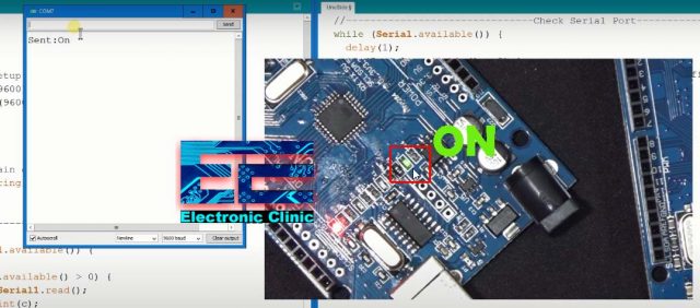
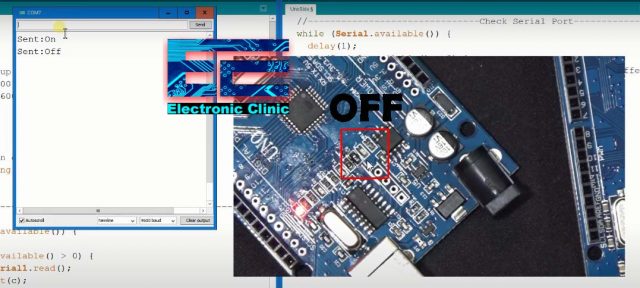
I uploaded the two programs, and completed my wiring as explained in the circuit diagram. I connected the Arduino Mega with the laptop and opened the serial monitor. I started typing the command on and off, and I was able to control the Arduino Uno onboard LED. As you can see in the images below.
“on” command
“off” command:
Serial Communication between two Arduino boards to control LEDs using Push Buttons:
Now, let’s take this whole thing to another level. This time we are going to control the LEDs connected with the Receiver Arduino Board using the push buttons connected with the Transmitter Arduino board. This time I designed a Proteus simulation for you guys, so don’t worry if you don’t have the LEDs and Arduino boards, you can use the Proteus simulation for practice.
Serial Communication between two Arduino’s Proteus Simulation:
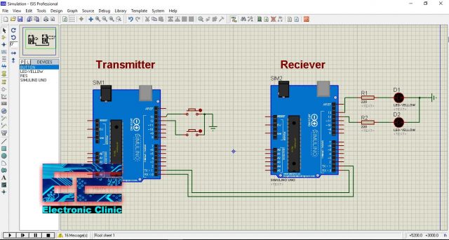
Download Proteus Simulation:
The two Arduino boards are connected serially. The TX of the Transmitter Arduino is connected with the RX of the Receiver Arduino. The RX of the Transmitter Arduino is connected with the TX of the Receiver Arduino. in the simulation it doesn’t matter if you don’t connect the grounds of both the Arduino’s, but in reality make sure you connect the grounds of both the Arduino’s.
Two push buttons are connected with the Transmitter Arduino pins 12 and 13. These push buttons are used to control the LEDs connected with the Receiver Arduino pins 12 and 13. The connections are pretty simple and straight forward.
Serial Communication between two Arduino boards, Transmitter Code:
|
1 2 3 4 5 6 7 8 9 10 11 12 13 14 15 16 17 18 19 20 21 22 23 24 25 26 |
// Transmitter int Button1 = 13; int Button2 = 12; void setup() { // put your setup code here, to run once: Serial.begin(9600); // for communication pinMode(Button1, INPUT_PULLUP); // for read button pinMode(Button2, INPUT_PULLUP); // for read button } void loop() { // put your main code here, to run repeatedly: if(digitalRead(Button1) == 0) { Serial.write('1'); } else if(digitalRead(Button2) == 0) { Serial.write('2'); } delay(20); // waitting message send } |
Serial communication between two Arduino boards, Receiver Code:
|
1 2 3 4 5 6 7 8 9 10 11 12 13 14 15 16 17 18 19 20 21 22 23 24 25 26 27 28 29 30 31 32 33 |
//Reciever int LED1 = 13; int LED2 = 12; char message; void setup() { // put your setup code here, to run once: Serial.begin(9600); // communication pinMode(LED1, OUTPUT); pinMode(LED2, OUTPUT); } void loop() { // put your main code here, to run repeatedly: if(Serial.available()) { message = Serial.read(); if(message == '1') { digitalWrite(LED1, 1); } else if(message == '2') { digitalWrite(LED2, 1); } } delay(20); digitalWrite(LED1, 0); digitalWrite(LED2, 0); } |
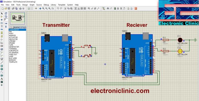
I hope you know how to generate the hex files, if you don’t know then you can use the hex files provided in the simulation folder along with the Arduino codes. The download link is given above. So, I added the Hex files and I was able to control the LEDs using the Push buttons. As you can see in the images given below.

With this my article on the Serial Communication between two Arduino boards come to an end. I hope you have learnt something new from this article.
Discover more from Electronic Clinic
Subscribe to get the latest posts sent to your email.


