Tetrode Construction and Characteristics in electronics
Last Updated on March 8, 2022 by Engr. Shahzada Fahad
Table of Contents
Description:
Tetrode Construction and Characteristics- in this article, you will learn about Tetrode construction and characteristics in full detail
Multi-Electrode Valves
As its name implies, multi-electrode valves are values or tubes consisting of more than one grid, due to which the acquisition of desirable characteristics, which cannot be achieved from triode, becomes possible. In other words, m.e.v tubes help in overcoming the deficiencies found in triodes.
Tetrode (having two grid and 4 electrodes), Pentodes (having 3 grids and 5 electrodes) are common examples of multi electrode valves (m.e.v). These are very effective and usually stable in operation compared to a triode. Apart from tetrode and pentode, m.e.v also includes hexode (tube with six electrodes) heptode (tube with seven electrodes) and octodes (tube with eight electrodes)
Construction of Tetrode
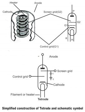
If an electrode is added to triode tube, this tube is called tetrad as it has 4 electrodes in it i.e. a tube which consists of 4 electrodes, is called tetrad. These 4 electrodes are anode, cathode, control grid and screen grid respectively. The basic difference between tetrad and triode is the existence of an additional grid in tetrad, which is called screen grid. From the structural point of view, just like control grid, screen grid is also made of wires coils or thin metal mesh.
However, screen grid is relatively loose and it is located between control grid and anode. It encompasses anode almost completely. It acts as a veil between control grid and anode that’s why it is known as a screen grid or just screen. As this grid was invented after grid control, it is also called grid 2 or G2, whereas control grid is called grid 1 or G1. It acts as an effective electrostatic field between anode and control grid. Its connections are put on pins at the bottom of tube. Normally, anode voltage keeps changing in tetrad tube; however, screen grid voltage remains constant. The structure and composition of tetrad has been shown in figure 1.16.
The necessity of invention of tetrad was felt because when triode tube is used as a radio frequency amplifier, a capacitance develops between triode grid and anode, the value of which is very low. Due to which the operation of amplification either becomes unstable or it fails completely and oscillation generated in amplifier. We know that greater the frequency, the lower will be the magnitude of reactance developed through capacitor.
That’s capacitance reactance and frequency are mutually inversely related i.e. XC= 1/2 fc,as a result, some portion of radio frequency voltage produced on anode, returns back to grid. The returning of circuit voltage back to it back is called feedback. The unpleasant effect of this feedback results in unstable operation of tube. The capacitance present between grid and anode has been shown in the figure through a diode line.
The value of capacitance from grid to anode in a triode normally ranges between 2-5 micros – micro farad. However, through fixing additional shielding electrodes in triode gives it the shape of tetrad and this capacitance reduces to 0.01 micro-micro farad. In this way, feedback operation finishes very effectively and using a radio frequency in amplifier, stable outcomes are achieved via tube. Effect of anode voltage on space charge ceases by reducing inter-electrode capacitance via screen grid. Further, variations in plate voltage also stop and anode current gets approximately stable/ constant. In this way, signal gain enhances.
In other words, the issue of feedback can easily be solved through screen grid. As screen grid is located between anode and control grid, it stabilizes the tube operation by removing capacitance existing between anode and control grid through effective shielding. Normally, screen grid is earthed through a large value capacitor (as shown in the figure). This capacitor provides an easy path to alternating voltages passing through screen towards earth. This capacitor is called screen bypass capacitor or just screen bypass. As the existence of screen creates hurdles in the flow electrons towards anode, it is therefore, necessary that positive voltages are also provided to screen. Screen grid not only reduces the mutual capacitance between anode and control grid. Its other great advantage is that it causes an unbelievable increase in amplification factor.
Characteristics of Tetrode
A Tetrode can also be operated like a triode. Its cathode is kept on earth potential. Control grid is supplied with lesser negative (bias) voltage whereas anode is provided sufficiently high (several hundred volts) positive voltage. The screen grid of Tetrode also kept on high positive potential with respect to cathode, however; its value is small compared to anode voltage. The positive voltages of screen grid help electrons moving swiftly towards anode, while keeping them on its path and as such cooperate with anodes’ electro static field. Some of the electrons generate currents through striking with grid screen, which is not beneficial. However, many of the electrons succeed in reaching anode and create current through passing the pores of screen.
Due to grid screen’s shielding effect, anodes’ electro static field has a very negligible impact on space charge near the cathode. As a result, changing anode voltage a little, anode current also goes through a small change. For generating a uniform change in anode current of a tetrode, quite a significant change in plate voltage is necessary compared to triode. As the ratio of a change in anode current due to a proportionate change in anode voltage, is called AC Anode Resistance, therefore anode resistance of a tetrode is much larger (0.5 – 1 mega ohms) as compared to triode.
The control grid of a tetrode affects the flow of anode current nearly in a similar manner as the control grid of a triode, which also controls the flow of anode current. The control grid of a triode is not shielded with the space charge through any screen grid. Thus a small change in the control grid voltage of a tetrode, leads to a large change in anode current (just like a triode) However, for creating a small change in tetrodes’ anode current, a significant change in anode voltage is required. We know that the mutual ratio of a small change in anode voltage to a small change in grid voltage, is called amplification factor (µ), which produce an equal change in anode current. Therefore, amplification factor of a tetrode is higher than amplification factor of a triode. However, it has to be remembered that the price for a high amplification factor of a tetrode has to be paid in the form of its high anode resistance. However, the Trans conductance (ratio of amplification factor and anode resistance) of a tetrode and triode is considered nearly identical. The process of fixing it in a circuit for understanding static characteristics of a tetrode has been explained in the figure 1.17. By keeping the control grid of a tetrode on a constant negative potential and screen grid (with respect to cathode) on a fixed positive potential, these characteristics can be achieved by studying changes in the screen current and plate current through changing plate voltage.
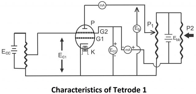
The potential of screen grid P2 is adjusted through replacement, whereas the value of plate voltage P1 is adjusted through replacing its place (As shown in the picture) the potential of screen grid is adjusted on a fixed value. After this plate voltage is changed. In the beginning, when the value of plate voltage is very small (and screen is on positive potential), electrons which reach plate by crossing screen grid due to potential found on screen grid, cause a current on the plate (i.e. plate current is produced due to it) Therefore, plate current increases up to a certain limit due to an increase in plate voltage, which leads to fall in screen grid current. If plate voltage is increased further, plate current starts diminishing instead of increasing, whereas screen grid current increases simultaneously. This happens due to the flow of secondary electrons. The electrons reaching plate have high velocities and as a greater potential exists on screen grid compared to plate, therefore screen grid attracts electrons which start retreating as a result of colliding with plate, thus plate current reduces and screen grid current increases. Such an operation continues till a particular range, as shown in figure 1.18. Plate current is assessed in this zone by subtracting secondary electrons reaching screen grid after their collision with plate from the primary electrons flowing towards the plate (i.e. plate current is determined in this zone through calculating the difference between primary electrons and secondary electrons).
In case further addition is made in plate voltage and it equalize with screen voltage, the gravitational force of anode on secondary electrons becomes greater due to the gravitational force on screen grid. Therefore, secondary electrons return towards anode once again, due to which anode current increases rapidly whereas screen current dwindles in the same ratio.
If anode voltage is increased further with respect to screen voltage, anode practically attracts all electrons coming from cathode. Further, in such a situation anode also start attracting electrons present on the screen grid and only those electrons are left behind on-screen grid, which are blocked and cannot pass through the screen. In such a situation, the value of anode current becomes too high (equivalent nearly to the total space current), while the value of screen current diminishes and it assumes a constant value. If a further increase is made in anode voltage, its impact is very negligible due the field effect of screen and anode current becomes nearly independent from the effect of anode voltage (in such a case, there will be no change on anode current of an increase in anode voltage) This characteristic of tetrode can be divided in the following 3 parts for the purpose of simplification.
- When the value of plate voltage is very small compared to screen grid voltage
- In case plate voltage equals screen grid voltage
- When the value of plate voltage is very large compared to screen grid voltage
These characteristics have been shown in figure 1.18. It is worth remembering that these characteristics of tetrode (i.e. amplification factor, high slope resistance and average values of mutual conductance) are specifically used for amplification of power and voltage.
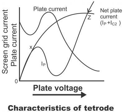
Negative Resistance
The characteristics curves of tetrode clearly indicate that despite an increase in its voltage, a decrease occurs in plate current in the XY region (opposite to ohm’s law). This negative current characteristic is known as negative resistance, while the tube instead of being known for being an apparatus of energy consumption, is referred to as a source of power (that’s it produces power in such a situation). Under particular conditions, anode current cannot remain stable due to such a behavior of tetrode as oscillation is produced. That’s the reason that the value of anode voltage is increased so much, that it does not reach negative resistance region through drop, due the presence of signal voltages on the grid. (In order to overcome this deficiency of tetrode, pentode tube came into being) However, it has to be kept in mind that this negative resistance characteristic of tetrode is used in special oscillation circuits.
Drawbacks of Tetrode
We know that by inserting a screen grid in tetrode tube a new problem comes up due to secondary emission. When the potential of screen grid exceeds plates’, several free electrons get attracted towards the screen. The plate current becomes lower due to this effect which also makes the working range of tube limited. Due to these undesirable characteristics, tetrode is used rarely. The following drawbacks are found in tetrode.
- Due to secondary emission, the variations in plate current and plate voltage are very limited in a tetrode. Therefore, the maximum output power of tetrode is less comparatively to triode.
- Oscillations are normally produced in circuit due to negative plate resistance while operating tube in the secondary emission region. Moreover, circuits composed of tetrode are usually unstable.
- If tetrode is to be used as an amplifier, its required static characteristics ought to be linear, parallel and mutually equal distance based. A high plate voltage is essential for fulfilling this condition, however, the plate voltage range in case of tetrode remains limited.
For electronics and programming-related projects visit my YouTube channel.
Previous article: Triode, Construction, Operation and Next article: Pentode
Discover more from Electronic Clinic
Subscribe to get the latest posts sent to your email.