Automatic Water Tap without using Arduino
Last Updated on August 23, 2024 by Engr. Shahzada Fahad
Table of Contents
Automatic Water Tap Project Description:
Automatic Water Tap– In this Tutorial, you will learn how to make a low-cost automatic water tap control system without using the Arduino. A few days back I got a message from Shafeeque who is from India and is one of my subscribers, that he had a problem in connecting the IR sensor with the relay to control a solenoid valve. I sent him some voice messages and explained the whole thing. He was actually inspired by this Project “Arduino based automatic water tap using a solenoid valve, infrared sensor, and a relay”. if you want to check this tutorial.
Shafique actually wanted to reduce the price so that’s why he decided not to use the Arduino and wanted to control the solenoid valve using only the IR sensor and a relay module. As per his requirement I sent him some circuit diagrams, he followed my instructions and completed his project successfully.
So this episode is all about how you can make the same automatic water tap control system without using the Arduino. Watch Video.
Amazon Links.
Disclosure: These are affiliate links. As an Amazon Associate I earn from qualifying purchases.
Circuit Diagram of the Automatic Water Tap control System:
This schematic is designed in cadsoft Eagle 9.1.0 version. If you want to learn how to make a schematic and PCB then watch my tutorial.
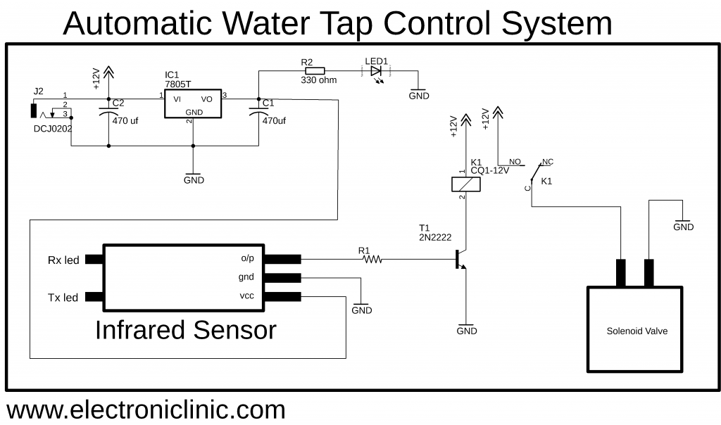
First of all, let’s start with the Power Supply. This is a 5v Regulated Power Supply based on the LM7805 voltage regulator. J2 is the female Power Jack and this is where we connect a 12v adaptor, Battery or a Solar Panel. By using the Solar Panel and a small battery you can reduce the electricity bill. The other advantage of using the Battery is, in case of an emergency situation, like for example if the power is disconnected from the utility company still the automatic water tap control system won’t stop working. In countries like Pakistan, India, Bangladesh, etc where people face heavy load-shedding battery is the best option. So J2 is the female power jack where we connect a 12v adaptor, a battery or a solar panel.
A 470uf capacitor is connected at the input side of the lm7805 voltage regulator. The middle leg of the voltage regulator is connected with the Ground of the Power supply, and also make sure you connect all the ground together. Another 470uf capacitor is connected at the output of the voltage regulator. A 330-ohm resistor is connected in series with a 2.5v led. This is a current limiting resistor.
The output of the voltage regulator is connected with the VCC pin of the infrared sensor. The Ground pin is connected with the Ground. while the output pin of the infrared sensor is connected with the base of the 2n2222 NPN transistor through a 10k resistor. The emitter of the 2n2222 NPN transistor is connected with the ground. While the collector of the transistor is connected with one leg of the relay coil and the other leg of the relay coil is connected with the 12 volts.
The normally open leg of the relay is connected with the 12 volts. The common leg or contact of the relay is connected with one wire of the solenoid valve, while the other wire of the solenoid valve is connected with the Ground.
Solenoid Valve used in the Automatic Water Tap control system:
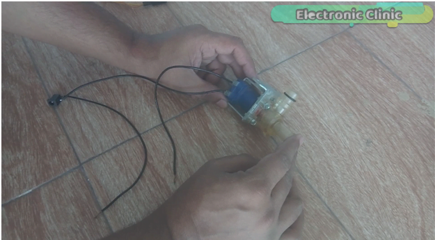
This is a 12v normally closed type Solenoid valve. In the Market, we have different types of solenoid valves, the size and shape can be different from this one, but the basic working principle of all the solenoid valves is exactly the same. As you can see this solenoid valve has two coil contacts and as you can see I have already soldered a female power jack. The ground pin of the female power jack is connected with this coil contact of the solenoid valve, while the other coil contact of the solenoid valve will be connected with the 12 volts. I cut this wire so that I can connect this with the relay normally open and the common contact.
Infrared sensor:
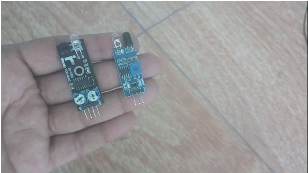
There are mainly two types of infrared sensors the one as you can see has three male header pins.
The rightmost leg is the VCC. The middle one is the ground while the leftmost leg is the Output.
While the other type has 4 male headers, the 4th one is the EN pin.
The first pin is the ground, the 2nd pin is the output while the 3rd pin is the VCC.
Both the Infrared sensors work in the same way. So it really doesn’t matter which type of infrared sensor you use.
Regulated 5v power supply:
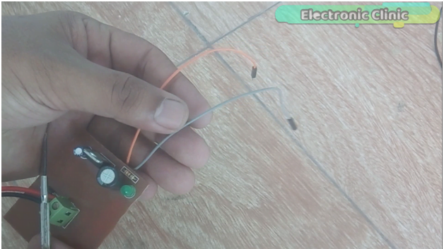
This is the regulated 5v Power Supply based on the LM7805 voltage regulator. The orange wire is the 5-volt wire while the grey wire is the ground wire.
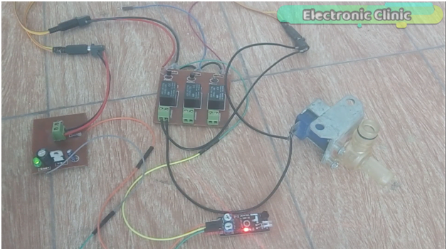
Relay Module:
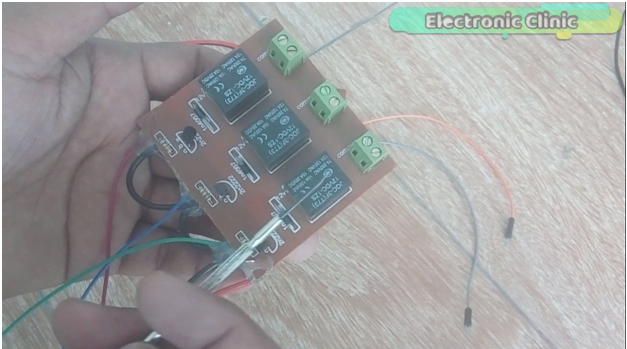
This is a three channel relay module, but we will use only one relay as we are going to control only one solenoid valve.
Infrared sensor Testing:
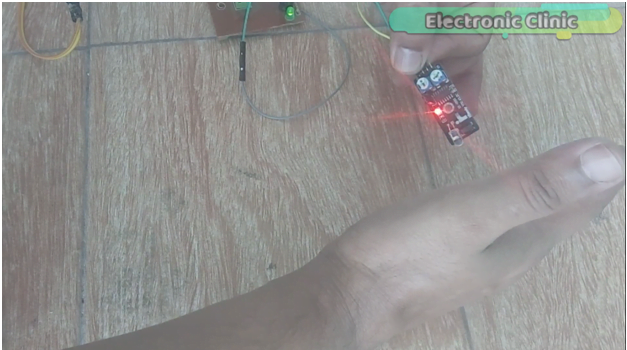
Let’s, first of all, check the infrared sensor. Connect the 5v and ground pins of the regulated 5v power supply with the VCC and ground pins of the infrared sensor. The red light Turns as when the infrared sensors detect any object. For the complete step by step explanation watch video tutorial given below.
Watch Video:
Related Projects in which Solenoid Valves are used:
Arduino Automatic Water Tap using Solenoid Valve
Arduino IOT Project: watering plants and soil moisture monitoring
Arduino Gas leakage detection and SMS alert MQ-2 sensor
Gas leakage detector and Automatic Solenoid Valve shut down using Arduino and MQ-2 Sensor
Discover more from Electronic Clinic
Subscribe to get the latest posts sent to your email.


Automatic Water Tap without using Arduino – HELP!!!!! I have been asking questions about this build and no one ever gets back to me. cbartlemay@yahoo.com
Mr Fahad, Your circuit diagram image is not readable on my monitor. It is out of focus.,.Can you re-post it?