ESP8266 WebServer Weather Station with Temperature, Pressure, and Rain Detection
Table of Contents
ESP8266 Webserver Weather Station:
ESP8266 WebServer Weather Station with Temperature, Pressure, and Rain Detection- In my previous article, I explained how to make a webserver based Home automation system using ESP32 WiFi + Bluetooth module. For demonstration purposes, I controlled 220Vac light bulbs.
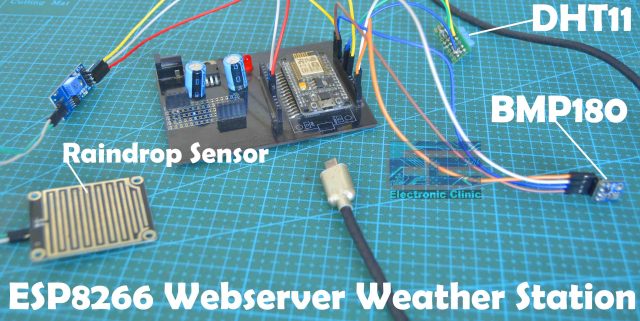
This project is also based on the webserver, but this time instead of controlling the Home appliances or other electrical loads we will be monitoring some sensors including the DHT11 Temperature and humidity sensor, BMP180 Sensor, and the raindrop sensor. Previously, I used the ESP32 WiFi + Bluetooth module but this time I decided to use the Nodemcu ESP8266 WiFi module. So, if you want to use the ESP32 Module then go ahead and read my previous article and if you want to use the Nodemcu ESP8266 then you should definitely read this article; as I will be explaining each and every detail.
In today’s article, you will learn how to make a Webserver based Weather station using Nodemcu ESP8266 WiFi module, DHT11 Temperature and Humidity sensor, BMP180 Sensor, and rain detector sensor. In this project the Nodemcu ESP8266 WiFi module is used as the Webserver which stores the HTML code and code for monitoring all these sensors. You don’t need to use use your computer or laptop as the webserver because you can use the low-cost ESP8266 WiFi module as the Webserver.
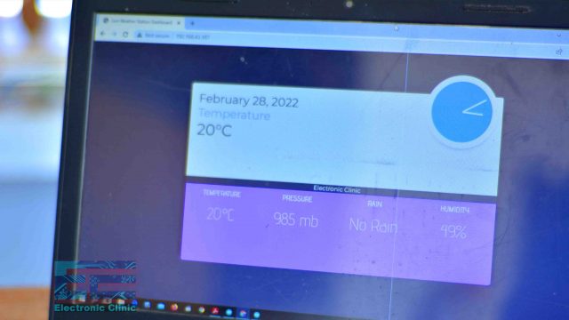
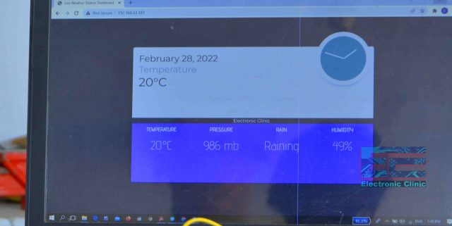
This weather station dashboard which you can see on the screen, its code is running on the ESP8266 WiFi module which you can modify to change the dashboard design and of course you can add code for monitoring some other sensors. You can open this weather station on multiple devices all you need is to enter the IP Address, I will talk about it in a minute.
Anyway, with this weather station I can monitor Temperature, Pressure, Rain Status, and Humidity. As I said earlier, if you want you can increase or decrease the number of sensors; all you need is to download the code given below, modify the code as per your requirement and that’s it. Anyways, Before, I am going to explain the circuit diagram and programming; first let’s watch this ESP8266 Webserver based Weather Station in action.
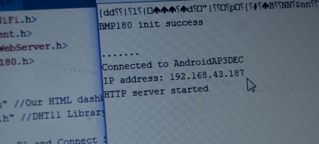
I connected all the sensors as per the circuit diagram which I will explain in a minute. Next, I connected my Nodemcu ESP8266 WiFi module with the Laptop to upload the code. Once the code was uploaded then I opened the Serial monitor, for the first few seconds I didn’t see any text on the Serial Monitor; If the same thing happens to you, all you need to do is to press the reset button on the Nodemcu ESP8266 WiFi Module and you will start receiving the data.
You can see the ESP8266 module is now connected with the WiFi router, you can also see the IP Address and the HTTP Sever Started message. You need this IP address for opening the Weather station dashboard. All you need is to select the IP address and then press Ctrl+c on the keyboard. Open the Web browser, paste the IP address, and then press Enter key on your keyboard.
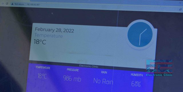
My ESP8266 Webserver based weather station can display all the sensor values. Now, let’s go ahead and check all the sensors one by one. Right now you can see the temperature is 18 Celsius and the Rain status is “No Rain”.
Altium Designer:
Altium Designer is the world’s most trusted PCB design system. Altium Designer enables engineers to effortlessly connect with every facet of the electronics design process. Over 35 years of innovation and development focused on a truly unified design environment makes it the most widely used PCB design solution. With Altium Designer you can create PCB designs with an intuitive and powerful interface that connects you to every aspect of the electronics design process. Route it your way through any angle, tune for the delay, Push, Slide, and Walkaround faster than ever. Interact and collaborate with mechanical designers like never before in a photo-realistic, 3D design environment. If you want to get started with the Altium designer, you can click on the get started.
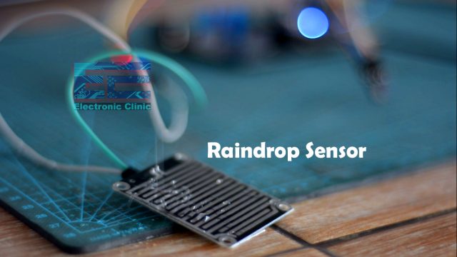
First, let’s start with the raindrop sensor. Currently, on the dashboard, you can see No Rain. Let’s sprinkle some water on the raindrop sensing pad which consists of the nickel-coated lines.
On the dashboard, you can see the Rain status changed from No Rain to Raining.
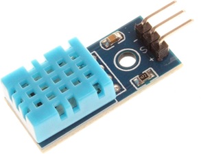
I also applied some heat to the DHT11 sensor. The Temperature and Humidity values which you can currently see on the Weather Station dashboard are from the DHT11 sensor. If you have used the DHT11 sensor then you should know this sensor is a bit slow. You can see rise in the temperature which means the DHT11 sensor is working.
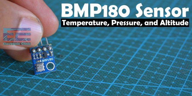
The pressure value which you can see on the screen is from the BMP180 sensor which is capable of measuring the temperature, pressure, and altitude. Right now, I am only reading the pressure value from the BMP180 Sensor, while the temperature I am reading from the DHT11 sensor.
My raindrop sensor module, BPM180 sensor module, and the DHT11 temperature and humidity sensor module are working perfectly. Now, you have got the idea of what exactly you are going to learn after watching this video. Without any further delay, let’s get started!!!
Amazon Links:
DHT11 Temperature and Humidity Sensor
Other Tools and Components:
Super Starter kit for Beginners
PCB small portable drill machines
*Please Note: These are affiliate links. I may make a commission if you buy the components through these links. I would appreciate your support in this way!
ESP8266 (NodeMCU):
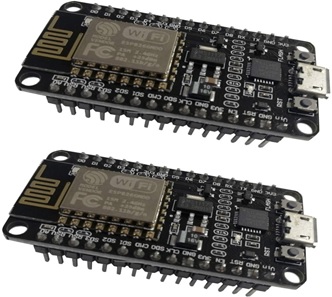
ESP8266 is a highly integrated chip designed for the needs of a new connected world. It offers a complete and self-contained Wi-Fi networking solution, allowing it to either host the application or to offload all Wi-Fi networking functions from another application processor.
ESP8266 has powerful on-board processing and storage capabilities that allow it to be integrated with the sensors and other application specific devices through its GPIOs with minimal development up-front and minimal loading during runtime. Its high degree of on-chip integration allows for minimal external circuitry, and the entire solution, including front-end module, is designed to occupy minimal PCB area.
Specifications:
Serial/UART baud rate: 115200 bps
Input power: 3.3V
I/O voltage tolerance: 3.6V Max
Flash Memory Size: 1MB (8Mbit)
WiFi security modes: WPA, WPA2
DHT11 Sensor:
- DHT11 digital temperature and humidity sensor is a digital signal output with a calibrated temperature and humidity combined sensor.
- It uses a dedicated digital modules and acquisition of temperature and humidity sensor technology to ensure that products with high reliability and excellent long term stability.
- Sensor consists of a resistive element and a sense of wet NTC temperature measurement devices, and with a high-performance 8-bit microcontroller connected.
- The product has excellent quality, fast response, anti-interference ability, high cost and other advantages.
- The single-wire wiring scheme makes it easy to be integrated to other applications and the simple communication protocol greatly reduces the programming effort required.
Raindrop Sensor:
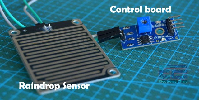
Basically raindrop sensor is a tool used for sensing rain which consists of two modules a rain board that detects the rain and the control module which is interfaced with the controller board. The raindrop sensing pad consists of Nickel-coated lines. It works on the principle of resistance. This Rain Sensor module allows to measure moisture via analog output pins and it provides a digital output when a threshold of moisture exceeds. When rain drops or water is present on the sensing pad it reduces the resistance because water is a conductor of electricity and presence of water connects nickel coated lines due to which its resistance reduces and this reduces the voltage drop across it.
All the four pins on the control board of the Raindrop sensor are clearly labeled as A0, D0, GND, and VCC. If you want to read the analog values then use the A0 pin or if you want to read the digital signal then use the D0 pin.
On the front side of the raindrop control board we have this blue color potentiometer which is used to set the threshold value.
BMP180 Sensor:
The BMP180 is a very interesting sensor by using this sensor we can get the temperature, pressure, and altitude. BMP180 is an I2C supported sensor. This is a high precision, small size, and ultra-low power consumption sensor. This sensor can be powered up using 1.8 to 3.6 volts. All the 4 pins are clearly labeled as VIN, GND, SCL, and SDA.
- BMP180 is a high-precision, small size, ultra-low power pressure sensor that can be used in mobile devices
- Its performance excellence, the absolute accuracy of the lowest can reach 0.03hPa, and low power consumption, only 3μA
- BMP180 powerful 8-pin ceramic leadless chip carrier (LCC) ultra-thin package, you can directly through the I2C bus connected with a variety of microprocessors
- Pressure range: 300 ~ 1100hPa (9000 meters above sea level ~ -500 meters)
- Low power consumption: 5μA in standard mode
Features:
1.8V to 3.6V Supply Voltage
Low power consumption – 0.5uA at 1Hz
I2C interface
Max I2C Speed: 3.5Mhz
Very low noise – up to 0.02hPa (17cm)
Full calibrated
Pressure Range: 300hPa to 1100hPa (+9000m to -500m)
ESP8266 Webserver Weather Station Circuit Diagram:
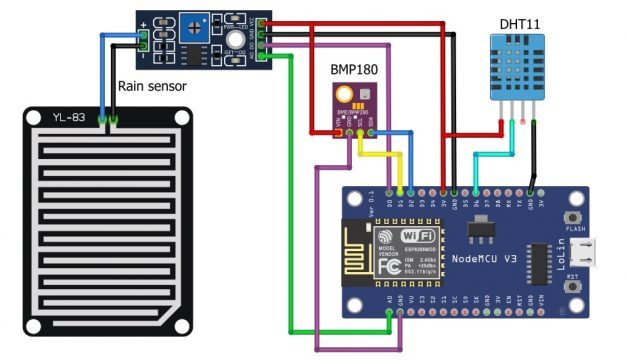
Now we will discuss how to interface these three sensors with the NodeMCU.
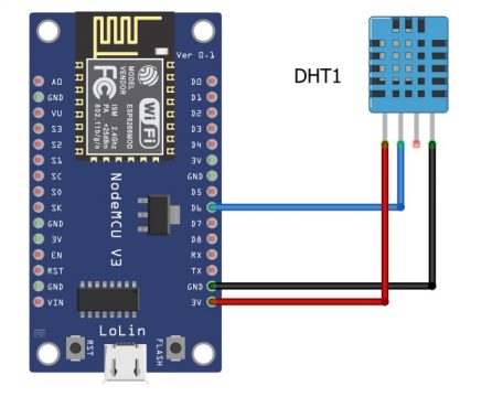
DHT11 interfacing with NodeMCU:
- Connect the VCC of the DHT11 with the 3.3V of the NodeMCU
- Connect the GND of the DHT11 with the ground of the NodeMCU
- Connect the signal pin of the DHT11 with the digital pin 6 of the NodeMCU
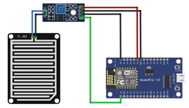
Rain senor interfacing with the NodeMCU ESP8266:
- Connect the VCC of the rain sensor with the 3.3V
- Connect the ground of the rain sensor with the ground of the NodeMCU
- Connect the digital pin of the rain sensor with the D0 of the NodeMCU
- Connect the A0 pin of the rain sensor with the A0 of the NodeMCU
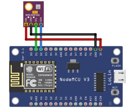
Interfacing BMP180 sensor with the NodeMCU:
- Connect the Vin pin of the BMP180 with the 3.3v of the NodeMCU
- Connect the ground pin of the BMP180 sensor with the ground of the NodeMCU
- Connect the SDA pin of the BMP180 sensor with the D2 pin of the NodeMCU
- Connect the SCL pin of the BMP180 sensor with the D1 pin of the NodeMCU
Complete Weather Station Circuit Diagram:
The circuit diagram is very simple. Connect the VCC pins of all the sensors with 3.3V pin of the Nodemcu ESP8266 WiFi module. Similarly, connect the GND pins of all the sensors with the GND of the Nodemcu module. We have multiple GND pins on the Nodemcu ESP8266 module; so, you can use any of the GND pins. Next, connect A0 pin of the Raindrop sensor control module with the A0 pin on the Nodemcu module and connect the D0 pin of the control board with the D0 pin of the ESP8266 WiFi module.
Connect the SCL and SDA pins of the BMP180 Sensor with the D1 and D2 pins of the Nodemcu Module. Finally, connect the data pin of the DHT11 Temperature and Humidity sensor with the D6 pin of the Nodemcu ESP8266 WiFi module. So, that’s all about the connections.
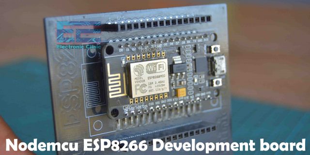
This is my Nodemcu ESP8266 WiFi module based development board which I use for testing my IoT based projects. If you want to make the same development board then you can watch my video.
If you are using the Nodemcu ESP8266 WiFi module for the first time then I highly recommend read my getting started article on the Nodemcu module in that article, I have explained how to install the Nodemcu board using the Arduino IDE.
Anyway, I connected all the sensors with the Nodemcu Module as per the circuit diagram and now let’s take a look at the programming.
ESP8266 Webserver Weather Station Programming:
Before, you start the programming, first of all, make sure you download all the necessary libraries.
The Webserver weather station project code is divided into two parts. The index.h consists of the code that creates the weather station dashboard for you. If you have some knowledge about the HTML coding then you can easily modify this code. Copy the following code, paste it in the notepad and save the file as the index.h.
Index.h code:
|
1 2 3 4 5 6 7 8 9 10 11 12 13 14 15 16 17 18 19 20 21 22 23 24 25 26 27 28 29 30 31 32 33 34 35 36 37 38 39 40 41 42 43 44 45 46 47 48 49 50 51 52 53 54 55 56 57 58 59 60 61 62 63 64 65 66 67 68 69 70 71 72 73 74 75 76 77 78 79 80 81 82 83 84 85 86 87 88 89 90 91 92 93 94 95 96 97 98 99 100 101 102 103 104 105 106 107 108 109 110 111 112 113 114 115 116 117 118 119 120 121 122 123 124 125 126 127 128 129 130 131 132 133 134 135 136 137 138 139 140 141 142 143 144 145 146 147 148 149 150 151 152 153 154 155 156 157 158 159 160 161 162 163 164 165 166 167 168 169 170 171 172 173 174 175 |
#include <ESP8266WiFi.h> #include <WiFiClient.h> #include <ESP8266WebServer.h> #include <SFE_BMP180.h> #include <Wire.h> #include "index.h" //Our HTML dashboard page #include "DHTesp.h" //DHT11 Library for ESP ///Connect SCL to D1 and Connect SDA to D2 #define LED 2 //On board LED #define DHTpin 12 // Digital pin 6 (GPIO 12) connected to the DHT sensor #define rainDigital D0 //#define DHTpin 5 //D1 of NodeMCU is GPIO5 SFE_BMP180 pressure; #define ALTITUDE 542.0 // Your Altitude in meters search in google DHTesp dht; //SSID and Password of your WiFi router const char* ssid = "AndroidAP3DEC"; const char* password = "electroniclinic"; ESP8266WebServer server(80); //Server on port 80 void handleRoot() { String s = MAIN_page; //Read HTML contents server.send(200, "text/html", s); //Send web page } float humidity, temperature; void handleADC() { char status; double T,P,p0,a; double Tdeg, Tfar, phg, pmb; status = pressure.startTemperature(); if (status != 0) { // Wait for the measurement to complete: delay(status); status = pressure.getTemperature(T); if (status != 0) { // Print out the measurement: Serial.print("temperature: "); Serial.print(T,2); Tdeg = T; Serial.print(" deg C, "); Tfar = (9.0/5.0)*T+32.0; Serial.print((9.0/5.0)*T+32.0,2); Serial.println(" deg F"); status = pressure.startPressure(3); if (status != 0) { // Wait for the measurement to complete: delay(status); status = pressure.getPressure(P,T); if (status != 0) { // Print out the measurement: Serial.print("absolute pressure: "); Serial.print(P,2); pmb = P; Serial.print(" mb, "); phg = P*0.0295333727; Serial.print(P*0.0295333727,2); Serial.println(" inHg"); p0 = pressure.sealevel(P,ALTITUDE); // we're at 1655 meters (Boulder, CO) Serial.print("relative (sea-level) pressure: "); Serial.print(p0,2); Serial.print(" mb, "); Serial.print(p0*0.0295333727,2); Serial.println(" inHg"); a = pressure.altitude(P,p0); Serial.print("computed altitude: "); Serial.print(a,0); Serial.print(" meters, "); Serial.print(a*3.28084,0); Serial.println(" feet"); } else Serial.println("error retrieving pressure measurement\n"); } else Serial.println("error starting pressure measurement\n"); } else Serial.println("error retrieving temperature measurement\n"); } else Serial.println("error starting temperature measurement\n"); humidity = dht.getHumidity(); temperature = dht.getTemperature(); Serial.print("H:"); Serial.println(humidity); Serial.print("T:"); Serial.println(temperature); //dht.toFahrenheit(temperature)); int rain = analogRead(A0); Serial.print("R:"); Serial.println(rain); int rainDigitalVal = digitalRead(rainDigital); String rainstatus; if(rainDigitalVal==1){ rainstatus="No Rain"; } else{ rainstatus="Raining"; } //Create JSON data String data = "{\"Rain\":\""+String(rainstatus)+"\",\"Pressuremb\":\""+String(pmb)+"\", \"Altitude\":\""+String(a)+"\", \"Temperature\":\""+ String(temperature) +"\", \"Humidity\":\""+ String(humidity) +"\"}"; //digitalWrite(LED,!digitalRead(LED)); //Toggle LED on data request ajax server.send(200, "text/plane", data); //Send ADC value, temperature and humidity JSON to client ajax request //delay(dht.getMinimumSamplingPeriod()); } void setup() { Serial.begin(115200); Serial.println(); // dht11 Sensor dht.setup(DHTpin, DHTesp::DHT11); //for DHT11 Connect DHT sensor to GPIO 17 pinMode(LED,OUTPUT); pinMode(rainDigital,INPUT); //BMP180 Sensor if (pressure.begin()) Serial.println("BMP180 init success"); else { Serial.println("BMP180 init fail\n\n"); while(1); // Pause forever. } WiFi.begin(ssid, password); //Connect to your WiFi network Serial.println(""); // Wait for connection while (WiFi.status() != WL_CONNECTED) { delay(500); Serial.print("."); } //If connection successful show IP address in serial monitor Serial.println(""); Serial.print("Connected to "); Serial.println(ssid); Serial.print("IP address: "); Serial.println(WiFi.localIP()); //IP address assigned to your ESP server.on("/", handleRoot); //Which routine to handle at root location. This is display page server.on("/readADC", handleADC); //This page is called by java Script AJAX server.begin(); //Start server Serial.println("HTTP server started"); } void loop() { server.handleClient(); //Handle client requests } |
Actual code:
This part of the code is the actual code which reads all the sensors “dht11 sensor, rain sensor, and bmp180 sensor” and then send the values to the Webserver based Weather station dashboard. Copy the following code, open the Arduino IDE, and save the file as you normally save the Arduino sketch.
|
1 2 3 4 5 6 7 8 9 10 11 12 13 14 15 16 17 18 19 20 21 22 23 24 25 26 27 28 29 30 31 32 33 34 35 36 37 38 39 40 41 42 43 44 45 46 47 48 49 50 51 52 53 54 55 56 57 58 59 60 61 62 63 64 65 66 67 68 69 70 71 72 73 74 75 76 77 78 79 80 81 82 83 84 85 86 87 88 89 90 91 92 93 94 95 96 97 98 99 100 101 102 103 104 105 106 107 108 109 110 111 112 113 114 115 116 117 118 119 120 121 122 123 124 125 126 127 128 129 130 131 132 133 134 135 136 137 138 139 140 141 142 143 144 145 146 147 148 149 150 151 152 153 154 155 156 157 158 159 160 161 162 163 164 165 166 167 168 169 170 171 172 173 174 175 |
#include <ESP8266WiFi.h> #include <WiFiClient.h> #include <ESP8266WebServer.h> #include <SFE_BMP180.h> #include <Wire.h> #include "index.h" //Our HTML dashboard page #include "DHTesp.h" //DHT11 Library for ESP ///Connect SCL to D1 and Connect SDA to D2 #define LED 2 //On board LED #define DHTpin 12 // Digital pin 6 (GPIO 12) connected to the DHT sensor #define rainDigital D0 //#define DHTpin 5 //D1 of NodeMCU is GPIO5 SFE_BMP180 pressure; #define ALTITUDE 542.0 // Your Altitude in meters search in google DHTesp dht; //SSID and Password of your WiFi router const char* ssid = "AndroidAP3DEC"; const char* password = "electroniclinic"; ESP8266WebServer server(80); //Server on port 80 void handleRoot() { String s = MAIN_page; //Read HTML contents server.send(200, "text/html", s); //Send web page } float humidity, temperature; void handleADC() { char status; double T,P,p0,a; double Tdeg, Tfar, phg, pmb; status = pressure.startTemperature(); if (status != 0) { // Wait for the measurement to complete: delay(status); status = pressure.getTemperature(T); if (status != 0) { // Print out the measurement: Serial.print("temperature: "); Serial.print(T,2); Tdeg = T; Serial.print(" deg C, "); Tfar = (9.0/5.0)*T+32.0; Serial.print((9.0/5.0)*T+32.0,2); Serial.println(" deg F"); status = pressure.startPressure(3); if (status != 0) { // Wait for the measurement to complete: delay(status); status = pressure.getPressure(P,T); if (status != 0) { // Print out the measurement: Serial.print("absolute pressure: "); Serial.print(P,2); pmb = P; Serial.print(" mb, "); phg = P*0.0295333727; Serial.print(P*0.0295333727,2); Serial.println(" inHg"); p0 = pressure.sealevel(P,ALTITUDE); // we're at 1655 meters (Boulder, CO) Serial.print("relative (sea-level) pressure: "); Serial.print(p0,2); Serial.print(" mb, "); Serial.print(p0*0.0295333727,2); Serial.println(" inHg"); a = pressure.altitude(P,p0); Serial.print("computed altitude: "); Serial.print(a,0); Serial.print(" meters, "); Serial.print(a*3.28084,0); Serial.println(" feet"); } else Serial.println("error retrieving pressure measurement\n"); } else Serial.println("error starting pressure measurement\n"); } else Serial.println("error retrieving temperature measurement\n"); } else Serial.println("error starting temperature measurement\n"); humidity = dht.getHumidity(); temperature = dht.getTemperature(); Serial.print("H:"); Serial.println(humidity); Serial.print("T:"); Serial.println(temperature); //dht.toFahrenheit(temperature)); int rain = analogRead(A0); Serial.print("R:"); Serial.println(rain); int rainDigitalVal = digitalRead(rainDigital); String rainstatus; if(rainDigitalVal==1){ rainstatus="No Rain"; } else{ rainstatus="Raining"; } //Create JSON data String data = "{\"Rain\":\""+String(rainstatus)+"\",\"Pressuremb\":\""+String(pmb)+"\", \"Altitude\":\""+String(a)+"\", \"Temperature\":\""+ String(temperature) +"\", \"Humidity\":\""+ String(humidity) +"\"}"; //digitalWrite(LED,!digitalRead(LED)); //Toggle LED on data request ajax server.send(200, "text/plane", data); //Send ADC value, temperature and humidity JSON to client ajax request //delay(dht.getMinimumSamplingPeriod()); } void setup() { Serial.begin(115200); Serial.println(); // dht11 Sensor dht.setup(DHTpin, DHTesp::DHT11); //for DHT11 Connect DHT sensor to GPIO 17 pinMode(LED,OUTPUT); pinMode(rainDigital,INPUT); //BMP180 Sensor if (pressure.begin()) Serial.println("BMP180 init success"); else { Serial.println("BMP180 init fail\n\n"); while(1); // Pause forever. } WiFi.begin(ssid, password); //Connect to your WiFi network Serial.println(""); // Wait for connection while (WiFi.status() != WL_CONNECTED) { delay(500); Serial.print("."); } //If connection successful show IP address in serial monitor Serial.println(""); Serial.print("Connected to "); Serial.println(ssid); Serial.print("IP address: "); Serial.println(WiFi.localIP()); //IP address assigned to your ESP server.on("/", handleRoot); //Which routine to handle at root location. This is display page server.on("/readADC", handleADC); //This page is called by java Script AJAX server.begin(); //Start server Serial.println("HTTP server started"); } void loop() { server.handleClient(); //Handle client requests } |
One point must be kept in mind that during writing the code the index library which consist of the html code and the main code file must be in the same folder. The project working I have already explained. For the practical demonstration watch the video tutorial given below.
Watch Video Tutorial:
