Raspberry Pi Pico ADC Reading an Analog Sensor
Last Updated on February 25, 2024 by Engr. Shahzada Fahad
Table of Contents
Raspberry Pi Pico ADC:
Analog Sensor Reading using Raspberry Pi Pico ADC– In this article, I am going to use this Potentiometer as the Analog sensor with the Raspberry Pi Pico Board. You know we have two types of sensors, Digital and Analog. Digital sensor I already explained with the help of a push button. Now, to explain how to read an analog sensor, this time I will use this Potentiometer with one of the Analog pins of the Raspberry Pi Pico. So, what I am going to do next is, I will read this Potentiometer and then I will display its value on the SSD1306 Oled display module. So, let’s go ahead and take a look at the circuit diagram.
Previous Articles:
Raspberry Pi Pico Pinout & Specs
Raspberry Pi Pico MicroPython and Thonny IDE Installation.
Raspberry Pi Pico Led examples.
Raspberry Pi Pico Digital Input.
Raspberry Pi Pico Oled Display Module SSD1306
Raspberry Pi Pico Temperature Sensor.
Raspberry Pi Pico Ultrasonic Sensor.
Raspberry Pi Pico PIR Motion Sensor.
Raspberry Pi Pico LDR Sensor, Day & Night Detection.
Amazon Links:
Other Tools and Components:
Super Starter kit for Beginners
PCB small portable drill machines
*Please Note: These are affiliate links. I may make a commission if you buy the components through these links. I would appreciate your support in this way!
Analog Sensor Interfacing with Raspberry Pi Pico ADC:
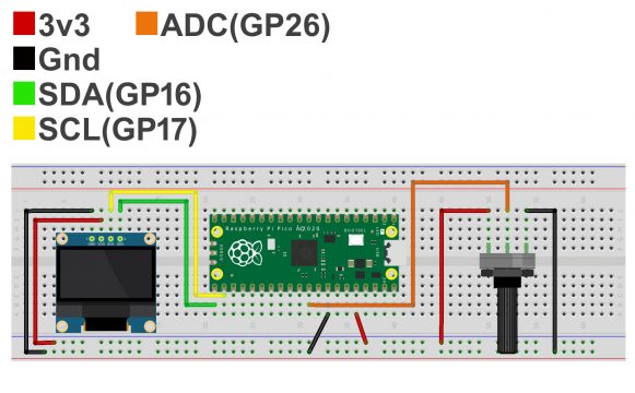
The SSD1306 Oled display module connections with the Raspberry Pi Pico remains exactly the same. Left leg of the potentiometer is connected with 3.3v, middle leg is connected with the Raspberry Pi Pico GP26 pin, and the rightmost leg is connected with the GND of the Pico board. Now let’s take a look at the programming.
Raspberry Pi Pico ADC Analog Sensor Programming:
|
1 2 3 4 5 6 7 8 9 10 11 12 13 14 15 16 17 18 19 20 21 22 23 24 25 26 27 28 29 30 31 32 33 34 35 36 37 38 39 40 |
from machine import Pin, I2C from ssd1306 import SSD1306_I2C from oled import Write, GFX, SSD1306_I2C from oled.fonts import ubuntu_mono_15, ubuntu_mono_20 import utime pot_Val = machine.ADC(26) WIDTH = 128 HEIGHT = 64 i2c = I2C(0, scl=Pin(17), sda=Pin(16), freq=200000) conversion_factor = 3.3 / 65535 oled = SSD1306_I2C(WIDTH, HEIGHT, i2c) while True: reading = pot_Val.read_u16() data = reading * conversion_factor oled.fill(0) write20 = Write(oled, ubuntu_mono_20) write20.text("Pot Val: ", 0, 0) write20.text(str(round(data,1)),0,20) oled.show() |
The SSD1306 Oled display module code remains exactly the same and this time I added code for reading the Potentiometer. I defined a pin to which the Potentiometer is connected. I named the GP26 pin as pot_Val.
|
1 2 3 |
reading = pot_Val.read_u16() data = reading * conversion_factor |
These two lines of codes read the potentiometer and applies the conversion_factor. These other lines of code simply print the value on the SSD1306 Oled display module. Now, let’s run this code.
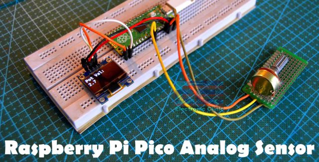
As you can see, by rotating the knob of the potentiometer, I am able to change the value. Now you can modify this code to control the LED brightness, you can control the speed of a DC motor, and so on.
Next article, Raspberry Pi Pico Onboard Temperature Sensor
Watch Video:
Discover more from Electronic Clinic
Subscribe to get the latest posts sent to your email.