Raspberry Pi Pico Onboard led Blinking Example
Table of Contents
Raspberry Pi Pico Led Blinking Example:
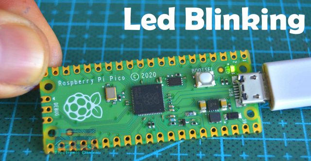
Raspberry Pi Pico Onboard led Blinking Example- Just like the Arduino, Raspberry Pi Pico also comes with the Onboard LED which is connected with the GP25. For the beginners it’s easier to start with controlling an LED rather than controlling and monitoring complex circuits. Before, you start controlling the Raspberry Pi Pico onboard LED, first, you will need to install the firmware, driver, etc and you will also need to install the IDE, in my case I will use Thonny IDE. I have talked about these things in detail, in my Raspberry Pi Pico complete course video. So, I highly recommend, you guys should definitely watch that video if you want to learn the most basic things.
If you are just getting started with the Raspberry Pi Pico then I highly recommend read my previous 3 articles.
Previous Articles:
Raspberry Pi Pico Pinout & Specs
Raspberry Pi Pico MicroPython and Thonny IDE Installation.
Raspberry Pi Pico Digital Input.
Raspberry Pi Pico Oled Display Module SSD1306
Raspberry Pi Pico ADC Analog Sensor
Raspberry Pi Pico Temperature Sensor.
Raspberry Pi Pico Ultrasonic Sensor.
Raspberry Pi Pico PIR Motion Sensor.
Raspberry Pi Pico LDR Sensor, Day & Night Detection.
Amazon Links:
Other Tools and Components:
Super Starter kit for Beginners
PCB small portable drill machines
*Please Note: These are affiliate links. I may make a commission if you buy the components through these links. I would appreciate your support in this way!
Raspberry Pi Pico Led Blinking Code:
|
1 2 3 4 5 6 7 8 9 10 11 12 13 14 15 16 17 |
import machine import utime led = machine.Pin(25, machine.Pin.OUT) while True: led.value(1) utime.sleep(1) led.value(0) utime.sleep(1) |
I have this very simple code for blinking the LED. The purpose of this code is to turn ON the LED for 1 second and then turn OFF the LED for 1 second. Let me explain the code.
|
1 |
import machine |
The machine module contains specific functions related to the hardware on a particular board.
|
1 |
import utime |
The utime module provides functions for getting the current time and date, measuring time intervals, and for delays.
|
1 |
led = machine.Pin(25, machine.Pin.OUT) |
The pin class has methods to set the mode of the pin (IN, OUT, etc) and methods to get and set the digital logic level.
|
1 2 3 4 5 6 7 8 9 |
while True: led.value(1) utime.sleep(1) led.value(0) utime.sleep(1) |
These lines of codes simply turn ON the Led for 1 second then turn OFF the led for 1 second. These lines of codes are executed again and again until we turn OFF the Raspberry Pi Pico board.
How to Run and Save the Code File:
To run this code on the Raspberry Pi Pico simply click on the Play button, you will be asked where to save the code file? In the computer or the Raspberry Pi Pico board, you need to select the Raspberry Pi Pico board, and the same thing I am going to do. I am going to click on the Raspberry Pi Pico.
Give a name to the file “Led_Blinking.py” and don’t forget to add the .py extension otherwise, the code won’t run on the Pico Board. As soon as you click on the OK button the LED will start blinking. The LED blinking delay time can be increased or decreased. Right now the LED is turning ON and turning OFF after every one second.
To stop the code simply click on the Stop button. For the practical demonstration watch video tutorial given at the end of this article.
When you save a file on the Raspberry Pi Pico board and you give it a name other than main.py as in my case I saved the file with the name Led_Blinking.py then such a file needs to be run manually which is really annoying. Go ahead and unplug your Raspberry Pi Pico board and then plug it again. The Led won’t work. Now, what to do, if we want to run the code automatically each time we connect the Raspberry Pi Pico board? For this you don’t have to make any changes in the code, all you need is simply resave the file but this time with the name main.py. So, if you want to run your code automatically on the Raspberry Pi Pico then give it the name main.py. Finally, click on the Ok button and you are done.
Now if you unplug your Raspberry Pi Pico board and Plug it again the code will automatically run. I am sure you have fully understood how to control the Onboard LED and how to save the code file on the Raspberry Pi Pico board. Let me remind you once again, if you face any issues then you can watch the complete video which is available at the end of this article. Anyway, you can always start with this simple getting started project to test your Raspberry Pi Pico board.
Anyway, so far everything is done correctly, the MicroPython installation is done correctly, the raspberry Pi Pico driver is working, and the Thonny IDE is working.
External LED with Raspberry Pi Pico:
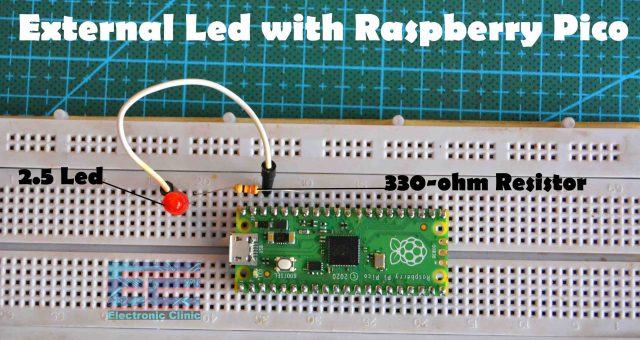
For this example, you will need a 2.5V LED and a 330-ohm resistor. So, let’s go ahead and take a look at the circuit diagram.
External Led with Raspberry Pi Pico Circuit:
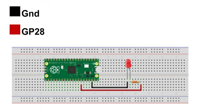
The Cathode leg of the LED is connected with the Raspberry Pi Pico GND pin and the Anode leg of the LED is connected with the GP28 through a 330 ohm current limiting resistor.
I did the same exact connections on the breadboard and now let’s take a look at the programming.
Raspberry Pi Pico Led Blinking Code:
|
1 2 3 4 5 6 7 8 9 10 11 12 13 14 15 16 17 18 19 20 21 22 23 |
from machine import Pin import utime led1 =Pin(28,Pin.OUT) delay = .40 while True: led1.value(1) utime.sleep(delay) led1.value(0) utime.sleep(delay) |
This is the same exact program that I used for controlling the Onboard LED. This time I made a few changes to make it more readable. This time I am using the GP28 to control the external LED. I also defined a variable delay, so by changing this value “delay = .40” over here you can control the Blinking rate of the LED. So, let’s go ahead and run this code. Click on the play button and save the file, the same way as I previously explained.
Anyway, I uploaded the code and the LED started blinking. I am sure now you have fully understood how to control an external LED.
Multiple LEDs with Raspberry Pi Pico:
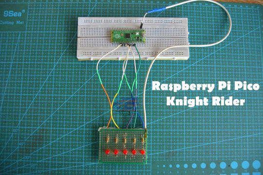
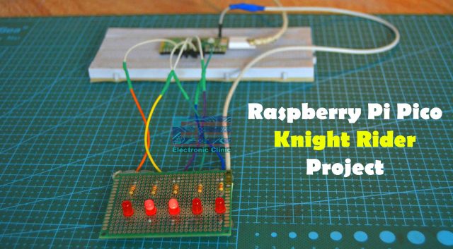
Now, in this third example, I am going to explain how to use multiple LEDs with Raspberry Pi Pico. I am going to create the Knight Rider LED effect using Raspberry Pi Pico and Multiple LEDs. So, first, let’s take a look at the circuit diagram.
Raspberry Pi Pico Knight Rider Circuit Diagram:
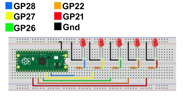
In the previous example, I used the GP28 pin of the Raspberry Pi Pico board to control the LED. This circuit is quite similar to the previous circuit the only difference is that this time I am using multiple LEDs. I am using the same 330-ohm current limiting resistors. The cathode legs of all the LEDs are connected with the GND pin of the Pico board and the Anode legs of all the LEDs are connected with GP21, 22, 26, 27, and 28 through these current limiting resistors. You can increase the number of LEDs as per your requirement. Make sure you keep an eye on the maximum current rating. If you need more current then you can use an external power supply.
I completed all the connections as per the circuit diagram and now let’s take a look at the programming.
Raspberry Pi Pico Knight Rider Programming:
|
1 2 3 4 5 6 7 8 9 10 11 12 13 14 15 16 17 18 19 20 21 22 23 24 25 26 27 28 29 30 31 32 33 34 35 36 37 38 39 40 41 42 43 44 45 46 47 48 49 50 51 52 53 54 55 56 57 58 59 60 61 62 63 64 65 66 67 68 69 70 71 72 73 74 75 76 77 78 79 80 81 82 83 84 85 86 87 88 89 90 91 92 93 94 95 96 97 98 99 100 101 102 103 104 105 106 107 108 109 110 111 112 113 114 115 116 117 118 119 120 121 122 123 124 125 126 127 128 129 130 131 132 133 134 135 136 137 138 139 140 141 142 143 144 145 146 147 148 149 150 151 152 153 154 155 156 157 158 159 160 161 162 163 164 165 166 167 168 169 170 171 172 173 174 175 176 177 178 179 180 181 182 183 184 185 186 187 188 189 190 191 192 193 194 195 196 197 |
from machine import Pin import utime led1 =Pin(28,Pin.OUT) led2 =Pin(27,Pin.OUT) led3 =Pin(26,Pin.OUT) led4 =Pin(22,Pin.OUT) led5 =Pin(21,Pin.OUT) delay = .06 while True: led1.value(1) led2.value(0) led3.value(0) led4.value(0) led5.value(0) utime.sleep(delay) led1.value(0) led2.value(1) led3.value(0) led4.value(0) led5.value(0) utime.sleep(delay) led1.value(0) led2.value(0) led3.value(1) led4.value(0) led5.value(0) utime.sleep(delay) led1.value(0) led2.value(0) led3.value(0) led4.value(1) led5.value(0) utime.sleep(delay) led1.value(0) led2.value(0) led3.value(0) led4.value(0) led5.value(1) utime.sleep(delay) led1.value(0) led2.value(0) led3.value(0) led4.value(0) led5.value(1) utime.sleep(delay) led1.value(0) led2.value(0) led3.value(0) led4.value(1) led5.value(0) utime.sleep(delay) led1.value(0) led2.value(0) led3.value(1) led4.value(0) led5.value(0) utime.sleep(delay) led1.value(0) led2.value(1) led3.value(0) led4.value(0) led5.value(0) utime.sleep(delay) led1.value(1) led2.value(0) led3.value(0) led4.value(0) led5.value(0) utime.sleep(delay) |
This code is similar to the previous code, the only difference is that this time I am using multiple LEDs to create the Knight Rider effect. I am turning ON only one LED at a time. You can see the code is quite lengthy, you can reduce this code to a few lines of code by using an array. For now, we will continue with this code. So, let’s go ahead and run this code.
It looks pretty awesome. You can increase or decrease the delay time in the same way as I previously explained. I am sure you have fully understood how to turn ON and turn OFF any GPIO Pin on the Raspberry Pi Pico.
Next article, Raspberry Pi Pico Digital Input
Watch Video:
