Salvage Electronic Parts #2: electronic components from Old Laptop Charger
Table of Contents
Description:
Salvage Electronic Parts from an Old Laptop Charger- So many useful electronic components can be salvaged from old electronic devices and machines. Today, we will see which useful electronic components can be salvaged from an Old Laptop Charger. First I will de-solder all the electronic components and then I will explain the most important components in detail. You can also watch my video in which I salvaged components and parts from a LaserJet printer.
Without any further delay let’s get started!!!
Note: for the de-soldering and explanation watch video tutorial given at the end of this article.
PS30SM100ST Power Schottky Rectifier:
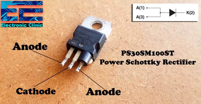
First, let’s start with the PS30SM100ST Power Schottky Rectifier. I salvaged two of these. This single Schottky rectifier is suited for high frequency switch mode power supply. This device is intended to be used in notebook, game station and desktop adaptors, providing in these applications a good efficiency at both low and high loads. As per the datasheet, Pin number 1 and pin number 3 are internally connected and are the anode pins, while pin number 2 or the middle leg is the cathode. So this is basically a dual Schottky diode with common cathode and is used in high current applications. This device has an average forward current of 30A and Repetitive peak reverse voltage of 100V.
The package consists of two diodes in parallel increasing the current rating and reducing the package size and cost. Since the Schottky diodes are faster and efficient (low voltage drop) they are commonly preferred over normal diodes provided the reverse voltage is need not be high.
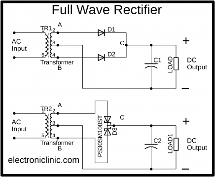
So, this is basically a full wave rectifier, as you can see
This is the Full wave rectifier, which I am sure you are quite familiar with, as you can see the two cathodes are connected together at point C and has two anodes A and B are connected with the secondary side of the centre tapped transformer. So, now I am sure you know how to use the PS30SM100ST Power Schottky Rectifier.
U4K8 Full Wave Bridge Rectifier:
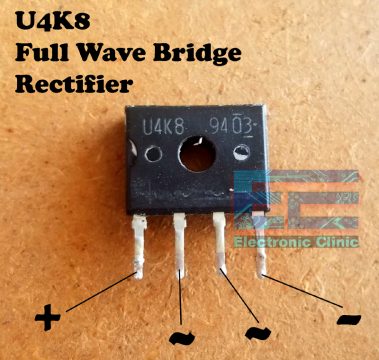
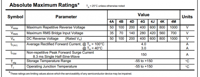
As per the datasheet the U4K8 Full Wave Bridge Rectifier has the maximum repetitive reverse voltage of 800 volts, Maximum RMS bridge input voltage is 560 Volts, and the DC reverse voltage is 800 Volts. The average rectified forward current is from 3 to 4 Amps.
U4K8 Pinout:
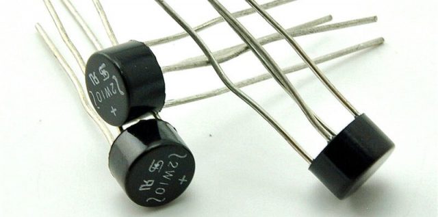
The first leg is the +, the middle two legs are the AC input lines, while the 4th leg is the – or GND leg. It’s use is just like the other bridge rectifiers like the one you can see below.
This one also have 4 legs which are labeled with the AC, +, and – signs. I have used this type of bridge rectifier in so many projects; I will add a few links at the end in the related projects section, if in case you want to check.
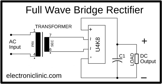
This is the basic circuit diagram that explains how the U4K8 is used. As you can see the Secondary side AC wires are connected with the AC pins of the U4K8 Full wave bridge rectifier while the + and – pins are connected with the + and GND legs of the decoupling capacitor. This capacitor is necessary for the smooth DC as this capacitor filter out the ac components.
U4K8 Absolute maximum ratings:
15N65C3 N-Channel Mosfet:
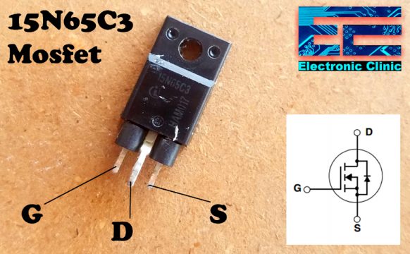
The 15N65C3 is a 16A, 650V N-Channel enhancement mode power field effect transistor, which provides superior switching performance, and withstand high energy pulse in the avalanche and commutation mode. This Mosfet is well suited for high efficient switched-mode power supplies and active power factor correction.
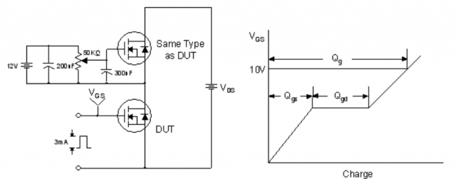
Gate Charge Test Circuit & Waveform
Resistive Switching Test Circuit & Waveforms
MKP-X2:
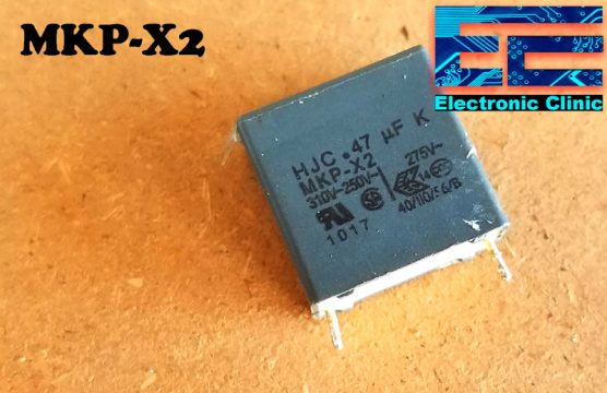
These are the Electromagnetic interference “EMI” or Radio-frequency interference “RFI” Suppression capacitors. X2 class is for the interference suppression and these capacitors are used across the AC input lines to suppress electrical noise by reducing the input impedance of the device incorporating the capacitor. The X2 type capacitors are used in applications where the peak voltage is < 1200V.
TTC 474 Thermistor:
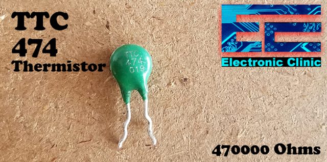
The TTC 474 is a thermistor “Temperature Sensor” very cost effective and has a wide resistance range of 470000 Ohms. The operating temperature range is -40 to +125C. This temperature sensor can be used in different projects like for example,
- A temperature controlled Fan.
- Over heat protection
- Temperature Alarm and so on
TTC 474 Thermistor based automatic FAN control Circuit diagram:
LM741 is basically an Operational Amplifier but it can also be used as the Voltage comparator. If you study in detail about the amplifiers you will come to know that any Operational Amplifier can be used as the voltage comparator, but it is not necessary that any comparator can be used as the Operational Amplifier.
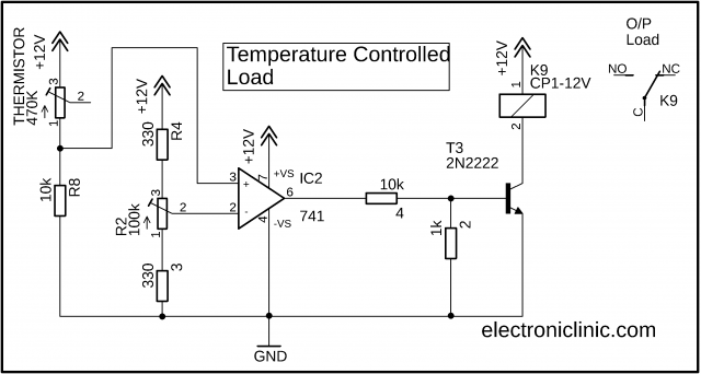
In the above circuit the LM741 Operational Amplifier is used as the voltage comparator. The TTC 474 Thermistor is connected in series with a 10 kilo Ohm resistor. The TTC 474 Thermistor and 10k resistor makes a voltage divider circuit. As the temperature varies so the resistance changes due to which the voltage changes. As you can see a wire from the middle of the TTC 474 Thermistor and 10k resistor is connected with the non-Inverting input pin of the LM741 Op Amp IC.
The voltage which is fed to the non-Inverting input of the LM741 IC is compared with the voltage which is coming from the R2 which is a 100K variable resistor or potentiometer. This variable resistor is used to set the reference voltage on the inverting input of the LM741 Op Amp IC. Two 330 Ohm resistors are connected in series with the 100k variable resistor, which protects the circuit from the short circuit.
Let’s say you rotate the knob of the variable resistor and the resistance get’s two low and as a result the 12v get’s short with the GND. In a situation like this it will damage the circuit. To protect the circuit from such situation the two resistors which are connected in series will provide resistance, so the voltage line will never short with the GND.
We have to voltages to compare let’s say
V1 = Reference voltage which is coming from the Variable resistor.
V2 = the voltage coming from the TTC 474 Thermistor and 10k resistor.
V1 and V2 will be compared using the LM741. The output of the LM741 will be High if
V1 > V2 and the output will be low if V1 < V2.
The V2 varies as the temperature varies. When V1 > V2 the output get High, and at the output we get voltage which is approximately equal to the input supply voltage which in our case is 12 volts. The output voltage of the LM741 IC is not exactly 12 volts it can be around 10 to 11 volts. So when the output is high we get around 12 volts.
At this point we are able to differentiate if the temperature is increased or decreased and accordingly we get 0 volts and 11 volts approximately.
Now the next step is to use this output voltage to control a Relay which can be used to control a light Bulb, Buzzer or an AC Fan or a DC Fan. So now we will make a driver for the relay. But if you look at the datasheet you will find that the output current of the LM741 IC is 25milliamps which is not enough to turn on a 12v relay. The relay I have used in this circuit needs around 32milliamps. So it means we will need some kind of driver to control the relay.
We can use a transistor with the LM741 IC. As you can see in the circuit diagram I have used 2n2222 NPN transistor. Now if you look at the datasheet of the 2n2222 NPN transistor you will find the 2n2222 base voltage should not exceed 6 volts. If you apply voltage greater than 6 volts it will damage the 2n2222 NPN transistor.
As we know the output voltage of the LM741 IC is around 12 volts when in ON state so if this voltage is directly connected with the base of the 2n2222 NPN transistor it will completely damage the transistor. Now to solve this problem we will need to use a voltage divider to reduce the voltage. So that’s the reason I used 10k and 1k resistors in series. Thus the base voltage never exceeds 6 volts. Now we can turn ON and Turn OFF the 2n2222 NPN transistor without any problem. The transistor will be used to control the 12v relay. This relay is of the type SPDT “Single Pole Double Throw”.
This relay can be used to control any type of bulb, AC or DC. You can also connect a buzzer instead using a bulb. Now it entirely depends on you for what purpose you are going to use this Circuit.
PC123 Optocoupler:
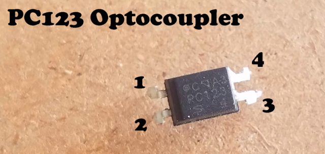
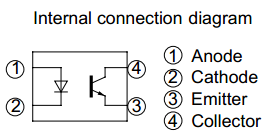
This is the PC123 Optocoupler.
PC123 internal connection diagram:
I have a very detail tutorial on how to use an Optocoupler to control an LED and how to control the speed of a DC Fan. This tutorial completely explains an Optocoupler.
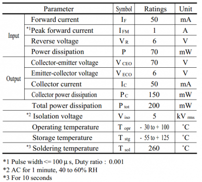
PC123 Optocoupler Absolute Maximum Ratings:
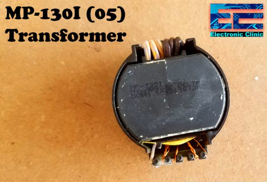
MP-130I (05) Transformer:
This is the MP-130I (05) Transformer with multiple taps. Using this transformer we can make a power supply for the Arduino and power up other electronic devices.
The other components that I salvaged were the Polarized and non-polarized capacitors, some heat sinks, some coils and an AC plug.
I hope you have learnt something. If you have any questions regarding these components you can let me know in a comment.
Watch Video Tutorial:
Related Projects:
Salvage mechanical and electronic parts from Laser Jet Printer:
IR Remote based DC Fan Speed control system using Optocoupler:
