Arduino Firebase Database, Students Attendance system using RFID and GSM
Table of Contents
Arduino Firebase Project Description:
Arduino Firebase, Students Attendance system using RFID and GSM– In this tutorial, you will learn how to make an advanced level student attendance system using Google Firebase Database, Arduino, GSM Sim900A Module, MFRC522 RFID Receiver Module, RFID Tags, and a 16×2 LCD. This is an IoT based project and used for monitoring the students’ attendance from anywhere around the world. With the help of this project, the students’ attendance is sent to the Google Firebase database through Nodemcu ESP8266 Wifi Module.
A few months back, I uploaded a very detailed getting started tutorial based on the Nodemcu ESP8266 Firebase. In This tutorial, I explained how to create your own Google firebase account and how to make your very first project to monitor a sensor in real-time from anywhere around the world. So, I highly recommend you should read my previous article on the Nodemcu ESP8266 Firebase, because in today’s article I will not explain the things which I have already explained in my previous tutorial. My previous tutorial on the Nodemcu ESP8266 Firebase got very popular on my YouTube channel “Electronic Clinic”.
Due to a lot of requests from my subscribers and followers, finally, I decided to make something complex. Don’t be afraid of the wiring and so many modules used in this project, I will go through all the details. So it really doesn’t matter if you have never used the GSM module, Nodemcu ESP8266, 16×2 LCD, and MFRC522 RFID Module.
Before I start explaining the circuit diagram and codes, first, let me explain how this project works, or you can watch the demonstration video given at the end of this article.
About the Arduino Firebase, Students Attendance System:
This is an RFID smart attendance system based on the Arduino Firebase. Parents get an instant SMS notification on their cell phones as soon as their child swipes the RFID card. This project is specially designed for the children safety; parents are informed whether they are in office or at home through an instant Real Time Automatic SMS. The school authorities can see the real time attendance on their computers or cell phones through a firebase database from anywhere around the world.
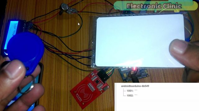
1001 and 1002 are the two students roll numbers. Currently, these fields are empty.
Swipe your card is written on the LCD which means that this system is ready for an RFID tag which can be an RFID key chain tag or an RFID card.
Each child will be given an RFID tag; it can be an RFID key chain or an RFID card. Now let’s practically check this system, as you can see in the picture above, in the database, the fields are empty. Let’s do it for the student number 1002. When I swiped the RFID card for student number 1002, attendance is marked was written on the LCD, the firebase database was updated and also a message was sent on the desired cell phone number. As you can see clearly in the picture below.
On the right side, you can see the student number 1002 is marked present.
Now this time let’s do it for student number 1001.
This system has an advantage even if you turn off the Arduino the Firebase database field values won’t be affected. In the video I practically demonstrated this, I turned off the Arduino and then again turned ON the Arduino, it had no effect on the Firebase data.
The Google Firebase database will be refreshed only when the Nodemcu ESP8266 module will be turned off and turned on again. So the Google Firebase database will only store the values for that day, the next day after restarting the Nodemcu ESP8266, the old attendance will be lost. As this system is only for the kids’ monitoring system on a daily basis. While the students’ actual attendance will be marked by the teachers in classrooms. The Arduino firebase database implementation is only for the inquiry purposes if in case the parents do not receive a message they can call the management, and then the management can double-check the attendance, they will verify through the firebase database and also from a teacher in the classroom.
The double-checking should be done by the management and the class attendance should be compared with the Google Firebase database to further ensure child safety.
There is a possibility that one student can swipe two or even more cards for his friends, while his friends are not physically present at school, so that’s why double-checking is a must and is the responsibility of the management.
Note: For the practical demonstration watch video given at the end of this article.
Without any further delay, let’s get started!!!
The components and tools used in this project can be purchased from Amazon, the components Purchase links are given below:
Arduino Nano USB-C Type (Recommended)
MFRC522 RFID module with tags:
Other Tools and Components:
ESP32 WiFi + Bluetooth Module (Recommended)
Super Starter kit for Beginners
PCB small portable drill machines
*Please Note: These are affiliate links. I may make a commission if you buy the components through these links. I would appreciate your support in this way!
About the Google Firebase Database:
Google Firebase is a Google-backed application development software used for creating, managing, and modifying data generated from any android/IOS application, web services, IoT sensors & Hardware. To learn more about the Google Firebase Console, you can read the official Google Firebase Documentation from Google Firebase.
Some of the most commonly asked questions about the Google Firebase Database.
What is Google Firebase Database?
The Firebase Realtime Database is a cloud-hosted database. When you build cross-platform apps with our iOS, Android, and JavaScript SDKs, all of your clients share one Realtime Database instance and automatically receive updates with the newest data.
What type of Database is Firebase?
Firebase is a Backend As A Service or BAAS, meaning it is a NoSQL data store that is in the cloud that your clients can access directly in realtime. Now this means Firebase has it’s own Realtime Database, Cloud Storage, Authentication, Hosting, and many other services.
Is Firebase better than SQL?
Unlike SQL there’s no schema for the database, no tables, no columns, it’s just a combination of key/value pairs. Firebase is based on a data structure used by the NoSQL database is vastly different from those used in a relational database. Some operations are faster in NoSQL than relational databases like MySQL.
Which is better Firebase or AWS?
If you’re a small team setting up, Firebase might serve you better than a heavy AWS setup. It also has a lower learning curve than AWS. On the flip side, Firebase makes it difficult to query larger datasets. Their database also doesn’t provide relational data, which could spell trouble for some newer companies.
Can I use Firebase for Free?
Yes, it’s free. You can use Analytics for advanced messaging – out of the box. Which products are paid? Firebase’s paid infrastructure products are the Realtime Database, Firebase Storage, Hosting, and Test Lab.
Is Firebase good for a large database?
The real-time functions in Firebase are not only suited for but designed for large data sets. The fact that records stream in real-time is perfect for this. Performance is, as with any large data app, only as good as your implementation.
Is Firebase a DBMS?
FireBase It’s a cloud service Also FireBase is a NoSQL database. In FireBase Data stored/processed in a cloud. FireBase is suitable for real-time applications. MySQL is a relational database management system (RDBMS)
Which language is used in Firebase?
The Firebase SDK supports programming in C++, Java, JavaScript, JavaScript/Node. js, Objective-C, and Swift. Angular, Backbone, Ember, and React are supported through bindings to the database.
Can Firebase Handle a million users?
This is possible since firebase is just a bucket of data that can be easily allocated for each user. Queries with limited sorting and filtering functionality can be performed with the firebase database. Cloud firestore assures automatic scaling and can handle 1 million concurrent connections and 10,000 writes/second.
Is Firebase secure?
1 Answer. The short answer is yes: by authenticating your users and writing security rules, you can fully restrict read / write access to your Firebase data. In a nutshell, Firebase security is enforced by server-side rules, that you author, and govern read or write access to given paths in your Firebase data tree.
Why Firebase is used in Android?
Firebase allows you to build apps that need authentication, database, file storage, analytics, and server-side functionality without having to own and manage infrastructure and software required for server-side support. Using firebase, you can access the google cloud store for storing images from your app.
How fast is Firebase realtime database?
Firebase uses document storage (JSON Documents), similar to MongoDB, so there are documents with fields and subdocuments, and nothing like rows or tables. Back to your question, yes Firebase is blazingly fast. I’ve used Firebase in building two apps of mine, and the response is amazing.
Is learning Firebase easy?
Yes, it is really easy for beginners. Firebase has very good documentation. It is easy to connect you application to Firebase. If you are an android developer using Android Studio, you can connect your app to Firebase with just a few clicks using assistant, without using a single line of code.
How to make the Google Firebase Account?
Create Google Firebase Database Account follow the same exact steps and then resume from here. After making the Google Firebase Database account, the next step is how to connect all the electronics. For the best understanding first let’s discuss each module in detail so that you can understand the circuit diagram.
About the GSM Sim900A Module:
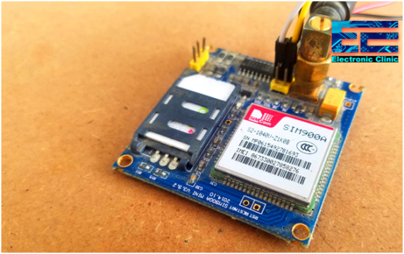
This is the GSM Sim900A Module. The first thing that you will notice about this GSM module is that, it has no onboard voltage regulator, so be very careful while applying the voltage; Because voltages greater than 5 volts can easily damage this module. The ideal voltage for this GSM module is 4.7v but you can easily power up this GSM Sim900A module using a 5v adaptor. if you don’t have a 5v adaptor then you can make your power supply using lm317t adjustable variable voltage regulator, I have a very detailed tutorial on lm317t explaining everything.
There are a few things that I really like about the GSM sim900A module which are
- This is the cheapest GSM module available on the market.
- Another cool thing is, it can be easily interfaced with 5V supported controller boards like Arduino Uno, Arduino mega, Arduino Nano etc, and also with 3.3v controller boards like Nodemcu ESP8266 Wifi Module and ESP32, etc. The GSM Sim900A module interfacing with Nodemcu ESP8266 is already done “Nodemcu ESP8266 with GSM”.
GSM Sim900A Specifications:
As I said earlier the GSM Sim900A Module has no onboard voltage regulator. Although it has a power supply pin which can be connected with the Arduino’s 5 volts. When no sensors are connected with the Arduino then you can Run this GSM module without any problem. But the time you start connecting different sensors with the Arduino, then Arduino cannot provide enough current to the Sim900A Module due to which the Arduino starts resetting.
So, my recommendation is use an external regulated 5v power supply.
GSM Sim900A Pinout:
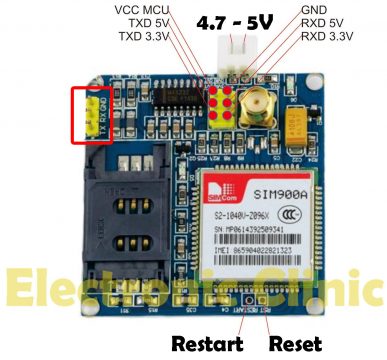
The white connector labeled with 4.7 – 5V, This is where we connect the external 5volt regulated power supply. It has a total of 9 male headers. The three male headers on the right side are not connected.
- Pin number 1 is the VCC which can be connected with the Arduino’s 5volts. In my case as I will power up this module using the external power supply so I will leave this pin unconnected.
- Pin number 2 is the ground, which will be connected with the Arduino’s ground.
- Pin number 3 is the 5v TXD,
- Pin number 4 is the 5v RXD,
- Pin number 5 is the 3.3v TXD, and
- Pin number 6 is the 3.3v RXD.
As Arduino is based on the 5v controller board so we will be using the 5v TXD and 5v RXD pins of the GSM Sim900A module.
If you want to study more about the GSM Sim900A a module, then read my article “GSM Sim900A with Arduino Complete Guide with GSM based Projects Examples“. This article explains everything about the AT commands and other things you want to learn.
About the MFRC522 RFID Module:
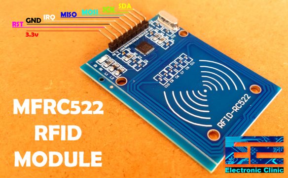
As you can see this is the MFRC522 RFID module. The MFRC522 is a highly integrated reader/writer IC for contactless communication at 13.56 MHz. This module has a total of 8 male headers which are clearly labeled as SDA, SCK, MOSI, MISO, IRQ, GND, RST, and 3.3V. As per the datasheet the typical voltage is 3.3V while the maximum voltage is 3.6 volts. This module can be easily powered up using the Nodemcu ESP8266 Wifi Module. But in this project I will interface this module with the Arduino.
Some of my previous projects based on the MFRC522 RFID Module.
· Arduino RFID Servo Motor Control system for Car Parking “MFRC522”
· RFID & GSM based student Attendance Alert message to parents
· RFID based students attendance system with message Alert
· Bike anti theft system using MFRC522 RFID module
· Raspberry Pi Home Automation using RC522 RFID, Smart Home
While using the MFRC522 RFID module with the Arduino, you need to know the identity numbers of the RFID tags. The RFID tags identity numbers can be found using the following Arduino code.
Find the RFID Tags Identity numbers:
|
1 2 3 4 5 6 7 8 9 10 11 12 13 14 15 16 17 18 19 20 21 22 23 24 25 26 27 28 29 30 31 32 33 34 35 36 37 38 39 40 41 42 43 44 45 46 47 48 49 50 51 52 53 54 55 56 57 58 59 60 61 62 63 64 65 66 67 68 |
/* * Pin layout should be as follows: * Signal Pin Pin Pin * Arduino Uno Arduino Mega MFRC522 board * ------------------------------------------------------------ * Reset 9 5 RST * SPI SS 10 53 SDA * SPI MOSI 11 51 MOSI * SPI MISO 12 50 MISO * SPI SCK 13 52 SCK * voltage 3.3v */ #include <SPI.h> #include <MFRC522.h> #define SS_PIN 10 #define RST_PIN 9 MFRC522 mfrc522(SS_PIN, RST_PIN); // Create MFRC522 instance. void setup() { Serial.begin(9600); // Initialize serial communications with the PC SPI.begin(); // Init SPI bus mfrc522.PCD_Init(); // Init MFRC522 card //Serial.println("Scan a MIFARE Classic PICC to demonstrate Value Blocks."); } void loop() { // Prepare key - all keys are set to FFFFFFFFFFFFh at chip delivery from the factory. MFRC522::MIFARE_Key key; for (byte i = 0; i < 6; i++) { key.keyByte[i] = 0xFF; } // Look for new cards if ( ! mfrc522.PICC_IsNewCardPresent()) { return; } // Select one of the cards if ( ! mfrc522.PICC_ReadCardSerial()) { return; } // Now a card is selected. The UID and SAK is in mfrc522.uid. // Dump UID Serial.print("Card UID:"); for (byte i = 0; i < mfrc522.uid.size; i++) { Serial.print(mfrc522.uid.uidByte[i] < 0x10 ? " 0" : " "); Serial.print(mfrc522.uid.uidByte[i], DEC); } Serial.println(); // Dump PICC type byte piccType = mfrc522.PICC_GetType(mfrc522.uid.sak); Serial.print("PICC type: "); Serial.println(mfrc522.PICC_GetTypeName(piccType)); if ( piccType != MFRC522::PICC_TYPE_MIFARE_MINI && piccType != MFRC522::PICC_TYPE_MIFARE_1K && piccType != MFRC522::PICC_TYPE_MIFARE_4K) { //Serial.println("This sample only works with MIFARE Classic cards."); return; } } |
About the 16×2 LCD:
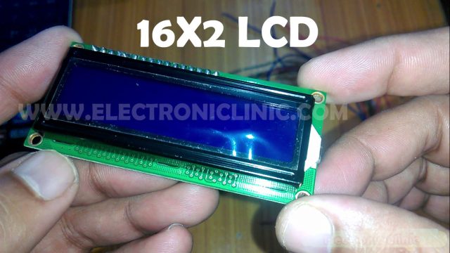
LCD stands for Liquid crystal display. 16×2 LCD is named so because; it has 16 Columns and 2 Rows. There are a lot of combinations available like 8×1, 8×2, 10×2, 16×1, etc. but the most used one is the 16×2 LCD. So, it will have 16×2 = 32 characters in total and each character will be made of 5×8 Pixel Dots.
Features of the 16×2 LCD module
- Operating Voltage of the 16X2 LCD is 4.7V to 5.3V
- Current consumption is 1mA without backlight
- This is an Alphanumeric LCD display module, which means you can display alphabets and numbers
- Consists of two rows and each row can print 16 characters.
- Each character is built by a 5×8 pixel box
- Can work on both 8-bit and 4-bit mode. “we will be using this LCD in 4-bit mode”.
- It can also display any custom generated characters. I will explain this in my upcoming tutorial.
- Available in Green and Blue Backlight
Read more about the 16×2 LCD Arduino interfacing and Programming.
Arduino Firebase Students Attendance System Circuit Diagram:
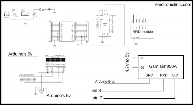
On the upper left side is the 5V regulated power supply based on the famous LM7805 voltage regulator. The positive and GND pins of the DC female power jack J1 are connected with the input and middle legs of the 7805 voltage regulator. Two 470uf capacitors are connected at the input and output sides of the voltage regulator. A 330 ohm resistor is connected in series with a 2.5V LED. This is a current limiting resistor. A wire from the output of the voltage regulator is connected with the Vin pin of the Nodemcu ESP8266 Wifi module while the ground of the power supply is connected with the ground pin of the Nodemcu module.
The Tx and Rx pins of the Nodemcu ESP8266 are connected with the Rx and Tx pins of the Arduino. Make sure the ground pin of the Arduino is connected with the ground pin of the Nodemcu module. The Arduino and Nodemcu module will communicate through serial communication.
Pin number1 and pin number 16 of the 16×2 LCD are connected with the ground.
Pin number 2 and pin number 15 of the 16×2 LCD are connected with the 5 Volts.
Pin 3 which is the contrast pin of the LCD is connected with the middle leg of the potentiometer. While the other two legs of the potentiometer or variable resistor are connected with the 5V and ground.
The RS pin of the LCD is connected with the analog pin A1 of the Arduino.
The EN pin of the LCD is connected with the analog pin A2 of the Arduino.
While the data pins D4 to D7 of the LCD are connected with the Arduino’s pins 6 to 3.
The TXD pin of the GSM Sim900A module is connected with the Arduino’s Pin number 7.
The RXD pin of the GSM Sim900A module is connected with the Arduino’s pin number 8.
The ground pin of the GSM module is connected with the ground pin of the Arduino.
The power supply pins of the GSM Sim900A module are connected with the 5V external power supply.
The MFRC522 RFID Module power supply pins are connected with the Arduino’s 3.3V and ground. The Rst pin of the MFRC522 RFID is connected with the Arduino’s Pin number 9. The ss pin of the MFRC522 RFID module is connected with the Arduino’s pin number 10. The MOSI pin is connected with the Arduino’s pin number 11. The MISO pin of the MFRC522 RFID module is connected with the Arduino’s pin number 12. The SCK pin of the MFRC522 RFID module is connected with the Arduino’s pin number 13.
So, that’s all about the circuit diagram.
Arduino Firebase Students Attendance System Programming:
The Arduino Firebase students attendance system is based on two programs. One program is written for the Arduino, while the other program is written for the Nodemcu ESP8266 Wifi Module. In this project the actual processing is done by the Arduino, while the Nodemcu Module is used to send the attendance data to the Google Firebase Database. So first let’s start with the Arduino Programming.
Before you start the programming first of all, make sure that you download all the necessary libraries.
GSM and RFID Arduino Programming:
|
1 2 3 4 5 6 7 8 9 10 11 12 13 14 15 16 17 18 19 20 21 22 23 24 25 26 27 28 29 30 31 32 33 34 35 36 37 38 39 40 41 42 43 44 45 46 47 48 49 50 51 52 53 54 55 56 57 58 59 60 61 62 63 64 65 66 67 68 69 70 71 72 73 74 75 76 77 78 79 80 81 82 83 84 85 86 87 88 89 90 91 92 93 94 95 96 97 98 99 100 101 102 103 104 105 106 107 108 109 110 111 112 113 114 115 116 117 118 119 120 121 122 123 124 125 126 127 128 129 130 131 132 133 134 135 136 137 138 139 140 141 142 143 144 145 146 147 148 149 150 151 152 153 154 155 156 157 158 159 160 161 162 163 164 165 166 167 168 169 170 171 172 173 174 175 |
/* terminal1 program ----------------------------------------------------------------------------- Nicola Coppola * Pin layout should be as follows: * Signal Pin Pin Pin * Arduino Uno Arduino Mega MFRC522 board * ------------------------------------------------------------ * Reset 9 5 RST * SPI SS 10 53 SDA * SPI MOSI 11 51 MOSI * SPI MISO 12 50 MISO * SPI SCK 13 52 SCK * voltage 3.3v * The reader can be found on eBay for around 5 dollars. Search for "mf-rc522" on ebay.com. */ // nodemcu esp8266 wifi module is connected with pin0 and pin1 of the arduino // connected the tx of nodemcu with rx of arduino and connect rx of nodemcu with tx of arduino // gsm module is connected with pin number 7 and pin number 8 of the arduino. #include <SPI.h> #include <MFRC522.h> #include <LiquidCrystal.h> #include <SoftwareSerial.h> SoftwareSerial SIM900(7, 8); // gsm module connected here String textForSMS; #define SS_PIN 10 #define RST_PIN 9 MFRC522 mfrc522(SS_PIN, RST_PIN); // Create MFRC522 instance. // lcd pins #define rs A1 #define en A2 #define d4 6 #define d5 5 #define d6 4 #define d7 3 // initialize the library with the numbers of the interface pins LiquidCrystal lcd(rs, en, d4, d5, d6, d7); // parents numbers String f1001 = "+923171956677"; // student1 father cell phone number String f1002 = "+923339022153"; // student2 father cell phone number String f1003 = "+923171956677"; // student3 father cell phone number void setup() { Serial.begin(9600); // Nodemcu is connected over here randomSeed(analogRead(0)); SIM900.begin(9600); // original 19200. while enter 9600 for sim900A SPI.begin(); // Init SPI bus mfrc522.PCD_Init(); // Init MFRC522 card //Serial.println("Scan a MIFARE Classic PICC to demonstrate Value Blocks."); // set up the LCD's number of columns and rows: lcd.begin(16, 2); // Print a message to the LCD. lcd.print("AttendanceSystem"); delay(3000); lcd.clear(); lcd.print("Swip Your Card"); delay(1000); } void loop() { // Prepare key - all keys are set to FFFFFFFFFFFFh at chip delivery from the factory. MFRC522::MIFARE_Key key; for (byte i = 0; i < 6; i++) { key.keyByte[i] = 0xFF; } // Look for new cards if ( ! mfrc522.PICC_IsNewCardPresent()) { return; } // Select one of the cards if ( ! mfrc522.PICC_ReadCardSerial()) { return; } // Now a card is selected. The UID and SAK is in mfrc522.uid. // Dump UID Serial.print("Card UID:"); for (byte i = 0; i < mfrc522.uid.size; i++) { // Serial.print(mfrc522.uid.uidByte[i] < 0x10 ? " 0" : " "); // Serial.print(mfrc522.uid.uidByte[i], DEC); } Serial.println(); // Dump PICC type byte piccType = mfrc522.PICC_GetType(mfrc522.uid.sak); // Serial.print("PICC type: "); //Serial.println(mfrc522.PICC_GetTypeName(piccType)); if ( piccType != MFRC522::PICC_TYPE_MIFARE_MINI && piccType != MFRC522::PICC_TYPE_MIFARE_1K && piccType != MFRC522::PICC_TYPE_MIFARE_4K) { //Serial.println("This sample only works with MIFARE Classic cards."); return; } // defining Cards here // student1 if( (mfrc522.uid.uidByte[0] == 224) && (mfrc522.uid.uidByte[1] == 154) && (mfrc522.uid.uidByte[2] == 156) && (mfrc522.uid.uidByte[3] == 124) ) // student1 card { lcd.clear(); lcd.print("AttendanceMarked"); delay(500); Serial.println("1001,"); delay(2000); // for gsm sendsms("Present", f1001); delay(3000); lcd.setCursor(0, 1); lcd.print("message sent"); delay(2000); lcd.clear(); lcd.print("Swip Your Card"); delay(1000); } // student2 if( (mfrc522.uid.uidByte[0] == 163) && (mfrc522.uid.uidByte[1] == 166) && (mfrc522.uid.uidByte[2] == 73) && (mfrc522.uid.uidByte[3] == 73) ) // student2 card { lcd.clear(); lcd.print("AttendanceMarked"); delay(500); Serial.println("1002,"); delay(2000); // for gsm sendsms("Present", f1002); delay(3000); lcd.setCursor(0, 1); lcd.print("message sent"); delay(2000); lcd.clear(); lcd.print("Swip Your Card"); delay(1000); } else Serial.println("unregistered user"); } void sendsms(String message, String number) { String mnumber = "AT + CMGS = \""+number+"\""; SIM900.print("AT+CMGF=1\r"); delay(1000); SIM900.println(mnumber); // recipient's mobile number, in international format delay(1000); SIM900.println(message); // message to send delay(1000); SIM900.println((char)26); // End AT command with a ^Z, ASCII code 26 delay(1000); SIM900.println(); delay(100); // give module time to send SMS // SIM900power(); } |
Nodemcu ESP8266 Firebase Database programming:
|
1 2 3 4 5 6 7 8 9 10 11 12 13 14 15 16 17 18 19 20 21 22 23 24 25 26 27 28 29 30 31 32 33 34 35 36 37 38 39 40 41 42 43 44 45 46 47 48 49 50 51 52 53 54 55 56 57 58 59 60 61 62 63 64 65 66 67 68 69 70 71 72 73 74 75 76 77 78 79 80 81 82 83 84 85 86 87 88 89 90 91 92 93 94 95 96 97 98 99 100 101 102 103 104 105 106 107 108 109 110 |
#include <ESP8266WiFi.h> #include <SoftwareSerial.h> #include <FirebaseArduino.h> #include <ArduinoJson.h> #include <ESP8266HTTPClient.h> // Set these to run example. #define FIREBASE_HOST "androidtoarduino-6b549.firebaseio.com" #define FIREBASE_AUTH "qPtNsvfbMKkcHp2FXqNvzCleuxNeEdTc9Zup1iJS" #define WIFI_SSID "ZONG MBB-E8231-6E63" #define WIFI_PASSWORD "08659650" String myString; // complete message from arduino, which consists of snesors data char rdata; // received characters int firstVal; void setup() { // Debug console Serial.begin(9600); // connect to wifi. pinMode(D0,OUTPUT); WiFi.begin(WIFI_SSID, WIFI_PASSWORD); Serial.print("connecting"); while (WiFi.status() != WL_CONNECTED) { Serial.print("."); delay(500); } Serial.println(); Serial.print("connected: "); Serial.println(WiFi.localIP()); Firebase.begin(FIREBASE_HOST, FIREBASE_AUTH); // students Firebase.setString("1001",""); Firebase.setString("1002",""); } void loop() { if (Serial.available() > 0 ) { rdata = Serial.read(); myString = myString+ rdata; // Serial.print(rdata); if( rdata == '\n') { String l = getValue(myString, ',', 0); firstVal = l.toInt(); Serial.println(firstVal); myString = ""; if ( firstVal == 1001) { // Firebase.setString("1001","Present"); Firebase.setString("1001/s_name","fawad"); Firebase.setString("1001/f_name","Jamshaid khan"); Firebase.setString("1001/class","4th"); Firebase.setString("1001/Attendance","present"); } if ( firstVal == 1002) { // Firebase.setString("1002","Present"); Firebase.setString("1002/s_name","mazhar"); Firebase.setString("1002/f_name","Javeid"); Firebase.setString("1002/class","4th"); Firebase.setString("1002/Attendance","present"); } } } } String getValue(String data, char separator, int index) { int found = 0; int strIndex[] = { 0, -1 }; int maxIndex = data.length() - 1; for (int i = 0; i <= maxIndex && found <= index; i++) { if (data.charAt(i) == separator || i == maxIndex) { found++; strIndex[0] = strIndex[1] + 1; strIndex[1] = (i == maxIndex) ? i+1 : i; } } return found > index ? data.substring(strIndex[0], strIndex[1]) : ""; } |
If you have any question regarding this project, let me know in a comment. Don’t forget to subscribe to my website and YouTube Channel “Electronic Clinic”.





where is the registed cards?
i checked your arduino code, in that i could not fine registed RFID cards. didnt you define those?