HZ1050 RFID Reader with Arduino, interfacing and programming
Last Updated on August 17, 2024 by Engr. Shahzada Fahad
Introduction:
HZ1050 RFID Reader- In this tutorial, you will learn how to use the HZ1050 RFID Reader with the Arduino and display the ID number of any RFID tag. I don’t know if the HZ1050 RFID Reader is as popular as the MFRC522 RFID Module. I have been using the RFID readers particularly the MFRC522 for quite a long time in different projects, which you can find in the related projects section given below.
This is my first tutorial on the HZ-1050 RFID reader. I came to know about this RFID reader through my friend Chimpo and decided to give it a try. A very cool thing about the HZ1050 RFID reader is that it does not need a lot of wires, this supports serial communication, so, you will need a maximum of 3 wires to connect this module.
Without any further delay, let’s get started!!!
Amazon links:
Arduino Nano USB-C Type (Recommended)
*Disclosure: These are affiliate links. As an Amazon Associate I earn from qualifying purchases.
HZ1050 RFID Reader:

HZ1050 Features:
Wigan 26/34 selectable by one jumper
Baud rate selectable
With light indicator
Small size and exquisite
HZ1050 Specifications:
Only read ID card(EM4100 4001, etc)
Card frequency: 125K
Read distance: 3-10cm
Read time: <0.2s
Output port: Wigan 26/34; Serial port UART output, TTL level
Power: 3.3-5.5V
Work temperature: -55~+125°C
Humidity: 20-90%RH for work, 10-90% for storage
Pressure: 86-106Kpa
Size: 29*62mm
Cable: 35*54mm
Cable lead: 10cm
HZ1050 RFID Reader Pinout:
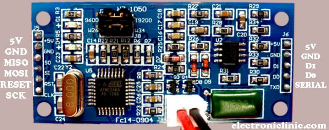
On the right side you have pins for the serial communication and on the left side you have pins for the SPI bus. In this tutorial you will go with the serial communication. We will be using pins available on the right side of the HZ1050 RFID Reader Module.
HZ1050 RFID Reader interfacing with Arduino:

you need only three wires to connect the HZ1050 RFID reader module with the Arduino. connect the 5v of the RFID reader with the Arduino’s 5V, Connect the GND pin of the HZ1050 with the GND pin of the Arduino, and finally connect the TXD pin of the RFID reader with the D2 pin of the Arduino. So, that’s all.
Everything is quite clear, on the right side we have the antenna where we swipe the RFID Card or Tag, in the middle, we have the RFID reader itself, and on the left side we have the Arduino Nano. You can follow the same exact connections using the Arduino Uno. Now, finally, we can start the programming.
Before, you start the programming; first of all, make sure that you download the wire.h library.
HZ1050 RFID Reader Arduino Programming:
|
1 2 3 4 5 6 7 8 9 10 11 12 13 14 15 16 17 18 19 20 21 22 23 24 25 26 27 28 29 30 31 32 33 34 35 36 37 38 39 40 41 42 43 44 45 |
#include <SoftwareSerial.h> #include <Wire.h> SoftwareSerial HZ1050(2, 3); // RX and TX int i, j; long value; void setup() { HZ1050.begin(9600); // start serial to RFID reader Serial.begin(9600); // start serial to PC } void loop() { value = NULL; //Serial.println(value); if (HZ1050.available() > 0) { value = NULL; for (j = 0; j < 4; j++) { i = HZ1050.read(); value += ((long)i << (24 - (j * 8))); } while (HZ1050.available() == 0) {}; Serial.print("UID:"); Serial.print(value); Serial.println(); if (value == 9157613 || value == 6028023) // Your UID's { Serial.print("Accepted"); // if correct uid is present do this... Serial.println(); //value = NULL; } else { Serial.print("Denighed"); delay(200); // if incorrect uid is present do this... Serial.println(); // value = NULL; } } } |
HZ1050 RFID Reader Arduino code explanation:
You can use the Arduino’s default serial port, but as I always say, never use the Arduino’s default serial port, it should only be used for the debugging purposes. As in Arduino Uno and Arduino Nano, we have only one serial port, so using the SofwareSerial library we can define multiple serial ports. So this is the reason I started off by adding the SoftwareSerial library.
#include <SoftwareSerial.h>
#include <Wire.h>
SoftwareSerial HZ1050(2, 3); // RX and TX
int i, j;
long value;
In the void setup() function, we simply activated the RFID reader and the serial communication. For now, I am using the same baud rate 9600.
void setup()
{
HZ1050.begin(9600); // start serial to RFID reader
Serial.begin(9600); // start serial to PC
}
In the void loop() function, we simply read the RFID card or tag and added an if condition to check if the desired card or tag is present.
void loop()
{
value = NULL;
//Serial.println(value);
if (HZ1050.available() > 0)
{
value = NULL;
for (j = 0; j < 4; j++)
{
i = HZ1050.read();
value += ((long)i << (24 – (j * 8)));
}
while (HZ1050.available() == 0) {};
Serial.print(“UID:”);
Serial.print(value);
Serial.println();
if (value == 9157613 || value == 6028023) // Your UID’s
{ Serial.print(“Accepted”); // if correct uid is present do this…
Serial.println();
//value = NULL;
}
else { Serial.print(“Denighed”);
delay(200); // if incorrect uid is present do this…
Serial.println();
// value = NULL;
}
}
}
HZ1050 RFID Reader Testing:
I uploaded the above program, opened the serial monitor, swiped my card, and I could see my RFID card number.

So, that’s all about the HZ1050 RFID Reader. I hope you have learned something from this article. If you have any questions regarding this project or any other project, let me know in a comment.
RFID Related Projects:
How to get RFID Chip Implant in Humans and practical uses with Arduino
Arduino Firebase Database, Students Attendance system using RFID and GSM
RFID and IoT, ESP8266 RFID based Remote Access Door Lock, RFID IoT
Raspberry Pi Home Automation using RC522 RFID, Smart Home
Raspberry Pi RFID RC522 NFC Reader, Tags Scanner python code
Arduino RFID Servo Motor Control system for Car Parking “MFRC522”
RFID & GSM based student Attendance Alert message to parents
RFID based students attendance system with message Alert
Bike anti theft system using MFRC522 RFID module
Discover more from Electronic Clinic
Subscribe to get the latest posts sent to your email.


HOW TO CONNECT THE RELAY MODULE FOR CONTROLLING THE ELECTRIC LOCK?
I had a few issues with your code returning error results. So a bit more work and I have changed it to return valid results. One of the main issues I found was the read loop was missing the delay while the serial port becomes availible. Anyway, here is the code, feel free to adapt and use:
#include <Wire.h>
#include <SoftwareSerial.h>
SoftwareSerial HZ1050(2, 3); // RX and TX
int i, j;
long value;
void setup()
{
HZ1050.begin(9600); // start serial to RFID reader
Serial.begin(9600); // start serial to PC
}
void loop()
{
value = NULL;
if (HZ1050.available() > 0)
{
value = NULL;
for (j = 0; j < 4; j++) {
while (HZ1050.available() == 0) {};
i = HZ1050.read();
value += ((long)i << (24 – (j * 8)));
Serial.print(i);
Serial.print(“.”);
}
if (value > 0) {
Serial.print(” > Valid > “);
} else {
Serial.print(” > Invalid > “);
}
Serial.println(value);
while (HZ1050.available() == 0) {};
}
}