Max30100 ESP8266 Nodemcu based Blood Oxygen & BPM Monitoring on Blynk
Last Updated on September 19, 2024 by Engr. Shahzada Fahad
Table of Contents
Max30100 ESP8266 Nodemcu, Description:
Max30100 ESP8266 Nodemcu- In this tutorial, you will learn how to monitor the Blood Oxygen & PBM on Blynk application and I2C supported 128×64 Oled display Module using Nodemcu ESP8266 Wifi Module and Max30100 Pulse Oximeter. A worldwide patient Monitoring system can be designed by using Max30100 with ESP8266 Nodemcu WiFi Module by the Espressif systems. For the best understanding I will share with you different codes and once you understand the very basics then finally, we make the complete project.
About the Sponsor, PCBWay:

High quality & Only 24 Hours Build time
The PCB board used in this project is sponsored by the PCBWay Company. Only 5 dollars for 10 PCBs and 30 dollars in total for 20 PCBs Assembly. Besides this PCBWay also provides a great variety of services including Aluminum PCB, Rigid-Flex, Metal Core, flexible, High Frequency, High-TG, Thick-Copper, HDI, and LED PCBs. The sign up process hardly takes 1 minute and you are welcomed with a 5 dollars welcome bonus, what are you waiting for go and get your first prototype order for free.
Download link of the Nodemcu library for Cadsoft eagle:
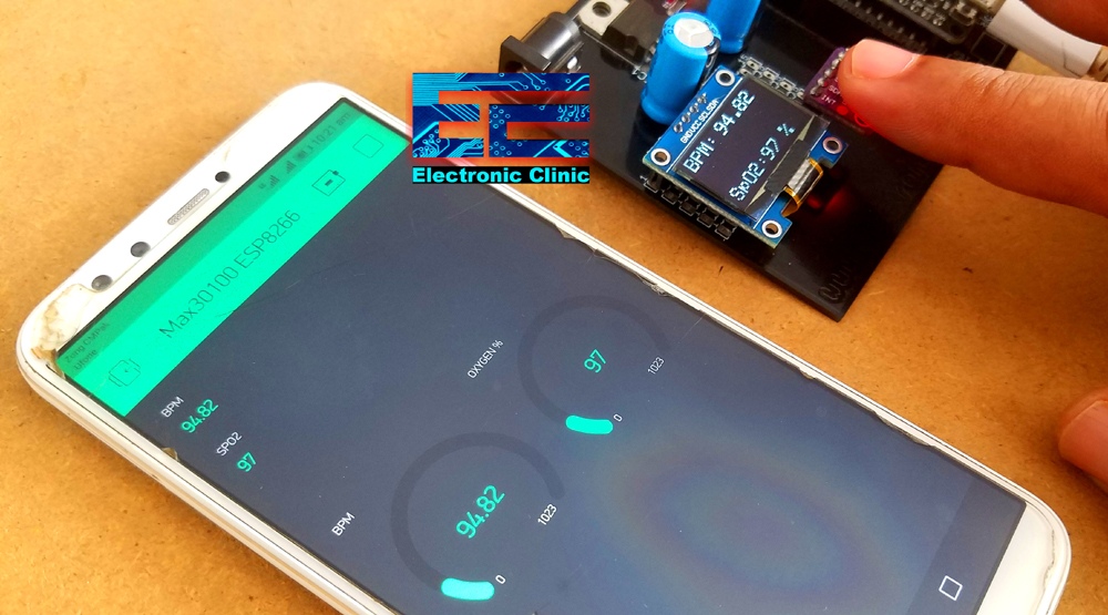
The Blood Oxygen and BPM or heart rate values can be monitored in real time using the Oled display module and the same values can also be monitored from anywhere around the world using the Blynk application. The main advantage of using the Oled display and the Blynk application is that, the house members can read the Blood Oxygen and BPM values directly on the Oled display module while the Doctor can monitor the Blood Oxygen and BPM or Heart values using the Blynk application from anywhere around the world if the Blynk application is connected with the internet, as this is an IoT based project. This is version 3.
In my previous tutorial, I monitored the Blood Oxygen and BPM values wirelessly using an Android application, Arduino Nano, and HC05 Bluetooth Module. In this tutorial, I also displayed the values on the I2C supported 16×2 LCD. This is not an IoT project. The android app can be used by family members for monitoring the patient. This is version 2.

In version 1, I already explained the very basics of the Max30100 Pulse Oximeter “Getting started with Max30100 Pulse Oximeter”. In this tutorial I interfaced the Max30100 pulse Oximeter with Arduino Uno and displayed the Blood Oxygen and Heart Rate information on the 16×2 LCD module and also fixed some of the common issues. I highly recommend read my previous articles on the Max30100.
In this tutorial, I will not explain the things which I have already covered in my previous articles. In this tutorial we will cover,
- Modified Circuit Diagram explanation
- Max30100 Nodemcu ESP8266 Programming
- Blynk application designing
- Soldering, and finally
- Testing
Without any further delay, let’s get started!!!
Note: this old version of the Blynk app is no more functional. For the blynk mobile App setup and Blynk.cloud dashboard setup ready my article on the New Blynk V2.0. In this article I have explained how to migrate your projects from Blynk 1.0 to the new Blynk V2.0. You can also watch the video.
Amazon Purchase Links:
SSD1306 128×64 Oled i2c display Module
*Please Note: These are affiliate links. I may make a commission if you buy the components through these links. I would appreciate your support in this way!
Max30100 Pulse Oximeter Pinout and Specs:

This is the Max30100 Pulse Oximeter used for measuring the Blood Oxygen concentration and Heart Rate or BPM. For more detailed discussion read my getting started article, Version 1.

As per the system block diagram which is available in the datasheet, it clearly shows that there should be small distance between the sensor and finger.
Max30100 Pulse Oximeter Sensor Technical Specification:
The MAX30100 operates from 1.8V and 3.3V power supplies.
Max30100 Applications
- Wearable Devices
- Fitness Assistant Devices
- Medical Monitoring Devices
Pinout of the Max30100 Pulse Oximeter:
As you can see clearly the GY-Max30100 Pulse Oximeter has a total of 5 male headers which are clearly labeled as VIN, GND, SCL, SDA, and INT. This is an i2c supported sensor and communicates with the Arduino board through i2c communication bus.
Nodemcu ESP8266 I2C Pins:
I have been using Nodemcu ESP8266 Wifi Module for quite a long time in different IoT based projects. I have already covered the extreme basics including the Nodemcu ESP8266 board installation, Blynk library downloading, and so many other things.
Just like the Arduino Uno, Nodemcu ESP8266 can also be used to communicate with the I2C supported devices.

If you look at the Pinout of the Nodemcu ESP8266, you will find D1 is the SCL and D2 is the SDA. So using these two pins multiple I2C supported devices can be connected with the Nodemcu ESP8266. In this project, we are using two I2C supported devices, the Oled Display module and the Max30100 Pulse Oximeter.
128×64 Oled I2C Supported Display:
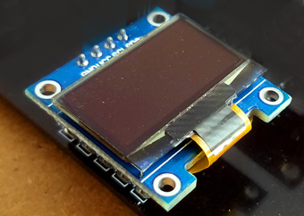
This is the I2C supported 128×64 Oled Display Module that we will use for displaying the Blood Oxygen and BPM values. If you have never used the Oled display module then ready my article on “Arduino Oled i2c Display 128×64 with examples, Wiring, and Libraries issues solved“. This Oled display module can be easily powered up using 3.3 volts.
Max30100 Interfacing with ESP8266 Nodemcu, Circuit Diagram:

The circuit diagram as you can see is very simple, there is nothing complicated. A 5V regulated power supply based on the LM7805 voltage regulator is used to power up the Nodemcu ESP8266 Module. You can use a wide range of input voltages greater than 7 volts and less than 26 volts. This way the whole project can be powered up using a 9v battery, 12v battery, 12v adaptor, Solar Panel etc. J1 is the female input power jack, this is where we connect the external power supply. Two 470uf 16v decoupling capacitors are connected at the input and output sides of the voltage regulator. A wire from the output of the voltage regulator is connected with the Vin pin of the Nodemcu ESP8266 Module. Make sure the GND of the Power supply is connected with the ground of the Nodemcu module.
D1 and D2 pins of the Nodemcu module which are the SCL and SDA pins are connected with the SCL and SDA pins of the Max30100 and Oled Display Module, while the voltage and ground pins of both the modules are connected with the 3.3V and ground pins of the Nodemcu ESP8266 wifi Module.
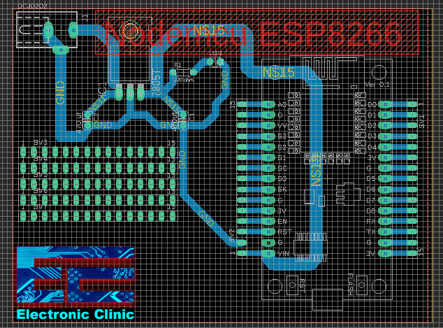
About the Nodemcu ESP8266 Power supply board:
To reduce the wiring, and to make everything look good, I designed my own PCB board for the Nodemcu ESP8266 Wifi module using the CadeSoft Eagle PCB designing software. The best thing about this PCB board is, it can be used as the development board. I have used this in so many IoT based projects.
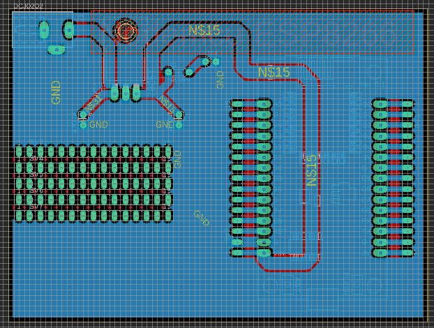
After I completed the PCB design, then I sent my PCB board Gerber files to the PCBWay Company for making High-Quality PCB’s. After generating the Gerber files, I double checked all the connections using the PCBWay online Gerber Viewer. After I was satisfied, then I placed an online order on the PCBWay official website.

I completed the soldering job as per the circuit diagram already explained. Make sure there is no short circuit between the SCL and SDA pins while soldering the wires for the Oled display module and the Max30100. These are the female headers I added for the Oled Display Module and the Max30100 pulse Oximeter.

These are the wires I used to connect the SCL and SDA pins of the Max30100 and Oled Display Module. The white and black wires are the 3.3V and GND connected with the power supply pins of both the modules.
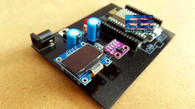
Finally, I connected the Oled display Module and the Max30100 Pulse Oximeter. So, this is how the final step look like, our hardware is ready. Now, before I am going to explain how to make the blynk application. First, I am going to share with you some basic codes that you can start with. Once you start getting the values then you can jump to the final code given below.
Max30100 ESP8266 Nodemcu Code1:
Following is the very basic code. The purpose of this code is to check if your Max30100 Pulse Oximeter Sensor is working. Connect your Nodemcu board with the computer and upload the following code. Open the serial monitor, and see if you can receive the Blood Oxygen and BPM values. If yes, then congrats you are good to go.
|
1 2 3 4 5 6 7 8 9 10 11 12 13 14 15 16 17 18 19 20 21 22 23 24 25 26 27 28 29 30 31 32 33 34 35 36 37 38 39 40 41 42 43 44 45 46 47 48 49 50 51 52 53 54 55 56 57 58 59 60 61 62 63 64 65 66 67 68 |
/* Download Libraries: https://www.electroniclinic.com/arduino-libraries-download-and-projects-they-are-used-in-project-codes/ */ #include <Wire.h> #include "MAX30100_PulseOximeter.h" #define REPORTING_PERIOD_MS 3000 PulseOximeter pox; uint32_t tsLastReport = 0; void onBeatDetected() { ; } void setup() { Serial.begin(115200); Serial.print("Initializing pulse oximeter.."); // Initialize the PulseOximeter instance // Failures are generally due to an improper I2C wiring, missing power supply // or wrong target chip if (!pox.begin()) { Serial.println("FAILED"); for(;;); } else { Serial.println("SUCCESS"); digitalWrite(1,HIGH); } pox.setIRLedCurrent(MAX30100_LED_CURR_24MA); // Register a callback for the beat detection pox.setOnBeatDetectedCallback(onBeatDetected); } void loop() { // Make sure to call update as fast as possible pox.update(); if (millis() - tsLastReport > REPORTING_PERIOD_MS) { // to computer Serial Monitor Serial.print("BPM: "); Serial.print(pox.getHeartRate()); //blue.println("\n"); Serial.print(" SpO2: "); Serial.print(pox.getSpO2()); Serial.print("%"); Serial.println("\n"); tsLastReport = millis(); } } |
For the next example we will need to make the Blynk application. Make sure the blynk application is installed on your cell phone, if not, watch my video tutorial, the link is already shared above.
Now, let’s make the Blynk application, follow the same exact steps.
Blynk Application Making:
I always first start with the Blynk application designing, this way I know which digital and virtual pins I have to use in the programming. Moreover this also helps me in checking my code, as I keep testing my project. Make sure you have downloaded and installed the Blynk application.
- First of all open the blynk application.
- Click on the new project and enter the project name as “MAX30100 ESP8266”. If you want you can select any other name. Later you can also modify the project name.
- Click on the choose device and select Nodemcu.
- Make sure the connection type is set to WIFI.
- Finally, click on the create button, an authentication token will be sent on your email id, which later will be used in the Nodemcu programming.
- Click anywhere on the screen and search for the Value Display Widget and add it to the screen. Add 2 Value Display Widgets. We will use these for displaying the BPM and the Blood Oxygen Concentration values.
- Again click on the screen and this time search for the Gauge and add it.
- Again click on the screen and this time add another Gauge widget to the screen. We will also use these two gauges for displaying the BPM and blood oxygen.
- After adding all the required widgets, next step is to do some settings.
- Click on the first Value Display widget, set the name as BPM, select input type as the virtual pin V2.
- Click on the 2nd Value display widget, set the name as SPO2, select the input type as the virtual pin V3.
- Click on the first Gauge, set the name as BPM, select the input type as the virtual V2.
- Click on the 2nd gauge, set the name as OXYGEN %, select the input type as the virtual V3.
Your application should look something like this.

If it’s hard for you to follow the steps, then you can watch video tutorial given at the end of this article. Application is ready; now let’s take a look at the programming.
Max30100 ESP8266 Nodemcu Code 2:
The following code is the modified version of the code given above. The purpose of this code is to send the Blood Oxygen SpO2 and BPM values to the computer serial monitor and also to the Blynk application. If you will study the code, you will find that both the codes are exactly the same, exact the libraries and some instructions added for the Nodemcu ESP8266 and Blynk application.
|
1 2 3 4 5 6 7 8 9 10 11 12 13 14 15 16 17 18 19 20 21 22 23 24 25 26 27 28 29 30 31 32 33 34 35 36 37 38 39 40 41 42 43 44 45 46 47 48 49 50 51 52 53 54 55 56 57 58 59 60 61 62 63 64 65 66 67 68 69 70 71 72 73 74 75 76 77 78 79 80 81 82 83 84 85 86 87 88 89 90 |
/* Download Libraries: https://www.electroniclinic.com/arduino-libraries-download-and-projects-they-are-used-in-project-codes/ */ #include <Wire.h> #include <ESP8266WiFi.h> #include <BlynkSimpleEsp8266.h> #include "MAX30100_PulseOximeter.h" #include <SimpleTimer.h> #include <ESP8266WiFi.h> #include <BlynkSimpleEsp8266.h> char auth[] = "FQ0c45MAYlKFLiJ8sVi7whav_HkyLkWt"; /* WiFi credentials */ char ssid[] = "AndroidAP7DF8"; char pass[] = "jamshaid"; #define REPORTING_PERIOD_MS 3000 SimpleTimer timer; PulseOximeter pox; uint32_t tsLastReport = 0; void onBeatDetected() { ; } void setup() { Serial.begin(115200); Blynk.begin(auth, ssid, pass); Serial.print("Initializing pulse oximeter.."); // Initialize the PulseOximeter instance // Failures are generally due to an improper I2C wiring, missing power supply // or wrong target chip if (!pox.begin()) { Serial.println("FAILED"); for(;;); } else { Serial.println("SUCCESS"); digitalWrite(1,HIGH); } pox.setIRLedCurrent(MAX30100_LED_CURR_24MA); // Register a callback for the beat detection pox.setOnBeatDetectedCallback(onBeatDetected); timer.setInterval(1000L, getSendData); } void loop() { timer.run(); // Initiates SimpleTimer Blynk.run(); // Make sure to call update as fast as possible pox.update(); if (millis() - tsLastReport > REPORTING_PERIOD_MS) { // to computer serial monitor Serial.print("BPM: "); Serial.print(pox.getHeartRate()); //blue.println("\n"); Serial.print(" SpO2: "); Serial.print(pox.getSpO2()); Serial.print("%"); Serial.println("\n"); Blynk.virtualWrite(V2,pox.getHeartRate() ); Blynk.virtualWrite(V3,pox.getSpO2()); tsLastReport = millis(); } } void getSendData() { ; } |
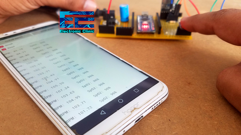
After uploading the above code, if you can monitor the Blood Oxygen SpO2 and BPM values on your cell phone using the Blynk application then your project is almost done. You can use this application for the monitoring. Are you ready for the final code? Good.
Max30100 ESP8266 Nodemcu Final Code:
This is the final code. With the help of this code, you can send the BPM and Blood Oxygen SpO2 values to the Blynk application and you can also print the SpO2 and BPM values on the Oled display module.
|
1 2 3 4 5 6 7 8 9 10 11 12 13 14 15 16 17 18 19 20 21 22 23 24 25 26 27 28 29 30 31 32 33 34 35 36 37 38 39 40 41 42 43 44 45 46 47 48 49 50 51 52 53 54 55 56 57 58 59 60 61 62 63 64 65 66 67 68 69 70 71 72 73 74 75 76 77 78 79 80 81 82 83 84 85 86 87 88 89 90 91 92 93 94 95 96 97 98 99 100 101 102 103 104 105 106 107 108 109 110 111 112 113 114 115 116 117 118 119 120 121 122 123 124 125 126 127 128 129 130 |
/* Download Libraries: https://www.electroniclinic.com/arduino-libraries-download-and-projects-they-are-used-in-project-codes/ */ #include <Wire.h> #include <Adafruit_GFX.h> #include <Adafruit_SSD1306.h> #include <ESP8266WiFi.h> #include <BlynkSimpleEsp8266.h> #include "MAX30100_PulseOximeter.h" #include <SimpleTimer.h> #include <ESP8266WiFi.h> #include <BlynkSimpleEsp8266.h> char auth[] = "JKbtWsou1V36Heq5nI6dAdF6t3ZCEKkQ"; /* WiFi credentials */ char ssid[] = "AndroidAP7DF8"; char pass[] = "jamshaid"; #define REPORTING_PERIOD_MS 3000 SimpleTimer timer; PulseOximeter pox; uint32_t tsLastReport = 0; void onBeatDetected() { ; } // for the OLED display #define SCREEN_WIDTH 128 // OLED display width, in pixels #define SCREEN_HEIGHT 64 // OLED display height, in pixels // Declaration for an SSD1306 display connected to I2C (SDA, SCL pins) #define OLED_RESET -1 // Reset pin # (or -1 if sharing Arduino reset pin) Adafruit_SSD1306 display(SCREEN_WIDTH, SCREEN_HEIGHT, &Wire, OLED_RESET); void setup() { Serial.begin(115200); Blynk.begin(auth, ssid, pass); display.begin(SSD1306_SWITCHCAPVCC, 0x3C); Serial.print("Initializing pulse oximeter.."); // Initialize the PulseOximeter instance // Failures are generally due to an improper I2C wiring, missing power supply // or wrong target chip if (!pox.begin()) { Serial.println("FAILED"); for(;;); } else { Serial.println("SUCCESS"); digitalWrite(1,HIGH); } pox.setIRLedCurrent(MAX30100_LED_CURR_24MA); // Register a callback for the beat detection pox.setOnBeatDetectedCallback(onBeatDetected); timer.setInterval(3000L, getSendData); display.clearDisplay(); display.setTextColor(WHITE); } void loop() { timer.run(); // Initiates SimpleTimer Blynk.run(); // Make sure to call update as fast as possible pox.update(); if (millis() - tsLastReport > REPORTING_PERIOD_MS) { // to android cell phone application Serial.print("BPM: "); Serial.print(pox.getHeartRate()); //blue.println("\n"); Serial.print(" SpO2: "); Serial.print(pox.getSpO2()); Serial.print("%"); Serial.println("\n"); Blynk.virtualWrite(V2,pox.getHeartRate() ); Blynk.virtualWrite(V3,pox.getSpO2()); tsLastReport = millis(); } } void getSendData() { // Oled display display.clearDisplay(); // display R G B Values display.setTextSize(2); display.setCursor(0,0); // column row display.print("BPM:"); display.setTextSize(2); display.setCursor(55, 0); display.print(pox.getHeartRate()); display.setTextSize(2); display.setCursor(0,50); display.print("SpO2:"); display.setTextSize(2); display.setCursor(60, 50); display.print(pox.getSpO2()); display.setCursor(95, 50); display.print("%"); display.display(); } |
Max30100 ESP8266 Nodemcu Code explanation:
For your project to work perfectly, you will need to download the following libraries.
|
1 2 3 4 5 6 7 8 9 10 11 12 13 14 15 16 17 18 19 |
#include <Wire.h> #include <Adafruit_GFX.h> #include <Adafruit_SSD1306.h> #include <ESP8266WiFi.h> #include <BlynkSimpleEsp8266.h> #include "MAX30100_PulseOximeter.h" #include <SimpleTimer.h> #include <ESP8266WiFi.h> #include <BlynkSimpleEsp8266.h> char auth[] = "JKbtWsou1V36Heq5nI6dAdF6t3ZCEKkQ"; |
this is the authentication code which is generated while making the blynk application. this authorization or authentication code is emailed on your register email id.
|
1 2 3 4 5 |
/* WiFi credentials */ char ssid[] = "AndroidAP7DF8"; char pass[] = "electroniClinic"; |
Your WiFi credential may be different from mine, so use your ssid and pass.
|
1 |
#define REPORTING_PERIOD_MS 3000 |
This defines the period, how often you want to send values to the blynk application. You can change this number. Currently I am sending values to the blynk application at 3 seconds interval.
|
1 2 3 4 5 6 7 8 9 10 11 12 13 14 15 16 17 18 19 20 21 22 23 24 25 26 27 28 29 30 31 32 33 34 35 36 37 38 39 40 41 42 43 44 45 46 47 48 49 50 51 52 53 54 55 56 57 58 59 60 61 62 63 64 65 66 67 68 69 70 71 72 73 74 75 76 77 78 79 80 81 82 83 84 85 86 87 88 89 90 91 92 93 94 95 96 97 98 99 100 101 102 103 104 105 106 107 108 109 110 111 112 113 114 115 116 117 118 119 120 |
SimpleTimer timer; PulseOximeter pox; uint32_t tsLastReport = 0; void onBeatDetected() { ; } // for the OLED display #define SCREEN_WIDTH 128 // OLED display width, in pixels #define SCREEN_HEIGHT 64 // OLED display height, in pixels // Declaration for an SSD1306 display connected to I2C (SDA, SCL pins) #define OLED_RESET -1 // Reset pin # (or -1 if sharing Arduino reset pin) Adafruit_SSD1306 display(SCREEN_WIDTH, SCREEN_HEIGHT, &Wire, OLED_RESET); void setup() { Serial.begin(115200); Blynk.begin(auth, ssid, pass); display.begin(SSD1306_SWITCHCAPVCC, 0x3C); Serial.print("Initializing pulse oximeter.."); // Initialize the PulseOximeter instance // Failures are generally due to an improper I2C wiring, missing power supply // or wrong target chip if (!pox.begin()) { Serial.println("FAILED"); for(;;); } else { Serial.println("SUCCESS"); digitalWrite(1,HIGH); } pox.setIRLedCurrent(MAX30100_LED_CURR_24MA); // Register a callback for the beat detection pox.setOnBeatDetectedCallback(onBeatDetected); timer.setInterval(3000L, getSendData); display.clearDisplay(); display.setTextColor(WHITE); } void loop() { timer.run(); // Initiates SimpleTimer Blynk.run(); // Make sure to call update as fast as possible pox.update(); if (millis() - tsLastReport > REPORTING_PERIOD_MS) { // to android cell phone application Serial.print("BPM: "); Serial.print(pox.getHeartRate()); //blue.println("\n"); Serial.print(" SpO2: "); Serial.print(pox.getSpO2()); Serial.print("%"); Serial.println("\n"); Blynk.virtualWrite(V2,pox.getHeartRate() ); Blynk.virtualWrite(V3,pox.getSpO2()); tsLastReport = millis(); } } |
The getSendData() function is a user-defined function, which has no return type and does not take any argument as the input. This function is used to display the BPM and SpO2 values on the Oled display module. The values on the Oled display are updated at an interval of 3 seconds.
|
1 2 3 4 5 6 7 8 9 10 11 12 13 14 15 16 17 18 19 20 21 22 23 24 25 26 27 28 29 30 31 32 33 34 35 36 37 38 39 40 41 42 43 44 |
void getSendData() { // Oled display display.clearDisplay(); // display R G B Values display.setTextSize(2); display.setCursor(0,0); // column row display.print("BPM:"); display.setTextSize(2); display.setCursor(55, 0); display.print(pox.getHeartRate()); display.setTextSize(2); display.setCursor(0,50); display.print("SpO2:"); display.setTextSize(2); display.setCursor(60, 50); display.print(pox.getSpO2()); display.setCursor(95, 50); display.print("%"); display.display(); } |
Nodemcu ESP8266 and Max30100 based SpO2 and BPM Monitoring, Final testing:

I was able to monitor the BPM and SpO2 values on the Oled display module and was able to monitor the same values on the Blynk application.
You can further modify this project by adding a temperature sensor and air quality monitoring sensor, etc. If you have any questions regarding this project, let me know in a comment.
Watch Video Tutorial:

Discover more from Electronic Clinic
Subscribe to get the latest posts sent to your email.

I am getting error “Initializing pulse oximeter..FAILED” in serial monitor. I used exact same model GY-MAX30100 purple color sensor. Any thoughts ?