Arduino MFRC522 RFID module Pinout, Interfacing, & how to read RFID
Last Updated on August 17, 2024 by Engr. Shahzada Fahad
Table of Contents
Arduino MFRC522 RFID Module, Overview:
Arduino MFRC522 RFID Module Pinout, Interfacing, and how to Read RFID Tags– MFRC522 RFID Module is no doubt an amazing and most commonly used RFID reader. I have used it in so many intermediate and advanced level projects e.g. “RFID Bike Anti-theft control System”, “Talking RFID System for Sports Bike”, “Students Attendance System with Firebase Database”, “RFID and IoT, Remote Door Lock Access”, “RFID Servo Control”, RFID and Raspberry Pi based Home Automation”, “RFID and GSM based Attendance System”, and so many other RFID based projects which you can check out by simply typing RFID in search box.
Today, I am writing this article especially for the beginners, although I have used the MFRC522 RFID module with Arduino and Nodemcu ESP8266, but still people ask me about the most basic things, which I believe I should have explained. But anyways, today, I will explain the very basic things that will help you to easily get started with the Arduino and MFRC522 RFID Module.
In this article, I will explain, the MFRC522 Pinout, how to Interface the MFRC522 with the Arduino? How to read the RFID Tags? And then how to use those RFID tags to perform specific tasks by the Arduino?
Without any further delay, let’s get started!!!
Amazon Links:
Arduino Nano USB-C Type (Recommended)
MFRC522 RFID module with tags:
*Disclosure: These are affiliate links. As an Amazon Associate I earn from qualifying purchases.
RFID MFRC522 Pinout:
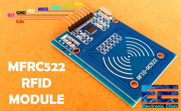
This is the MFRC522 RFID module that we will be using with the Arduino Uno. RFID Means Radio frequency identification. RFID uses electromagnetic fields to transfer data over short distances. You can use an RFID system to open a door, It can be used to make a student attendance system, It can be used to control a machine; it can be used in cars and bikes for Anti-theft protection. Some of the projects links I have already shared above.
The first pin is the vcc and this will be connected with 3.3v of the Arduino.
Pin number 2 is the RST or reset.
Pin number 3 is the ground.
While the MISO pin, MOSI PIN, SCK pin and the SS or SDA pin, these four pins are the SPI pins and will be connected with the Arduino SPI pins.
In Arduino the SPI pins are,
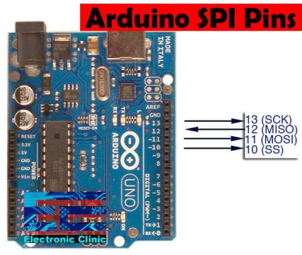
Pin number 13 is the SCK
Pin number 12 is the MISO
Pin number 11 is the MOSI and
Pin number 10 is the SS or SDA.
What is SPI?
SPI stands for “Serial Peripheral Interface”. It is a synchronous serial data bus, data can travel in both directions at the same time, as opposed to (for example) the I2C bus that cannot do so. To allow synchronous data transmission, the SPI bus uses four wires. They are called:
MOSI: Master-out, Slave-in. This line carries data from our Arduino to the SPI-controlled device(s);
MISO: Master-in, Slave out. This line carries data from the SPI-controlled device(s) back to the Arduino;
SS: Slave-select. This line tells the device on the bus we wish to communicate with it. Each SPI device needs a unique SS line back to the Arduino;
SCK: Serial clock.
While the last pin IRQ is not used.
MFRC522 Arduino Wiring, Circuit Diagram:
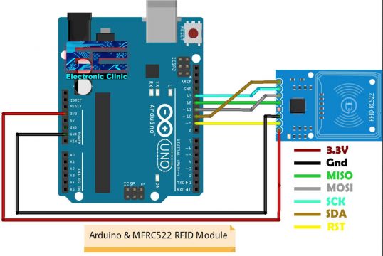
The interfacing is really easy, as this module has male header pin’s, so we can use male to female type jumper wires to connect this RFID module with Arduino.
First of all, connect the VCC of the MFRC 522 RFID module with 3.3v of the Arduino
Now connect the reset pin of the MFRC 522 RFID module with pin 9 of the Arduino
Now connect the Ground pin of the MFRC 522 RFID module with the ground of the Arduino
Now connect the MISO pin of the MFRC 522 RFID module with pin 12 of the Arduino
Now connect the MOSI pin of the MFRC 522 RFID module with pin 11 of the Arduino
Now connect the SCK pin of the MFRC 522 RFID module with pin 13 of the Arduino
And now finally connect the SS or SDA pin of the MFRC 522 RFID module with pin 10 of the Arduino. So that’s all about the interfacing.
How to Read RFID Tags?
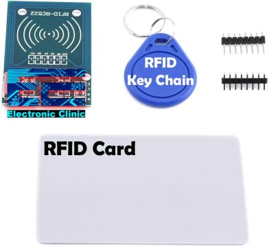
Usually the MFRC522 RFID Reader comes with two RFID Key chains and one white color RFID Card. The RFID Number or the Identity number is not printed on the key chains and RFID cards, so this is the reason majority of the beginners get confused. Before you can use your RFID key chains and RFID cards to mark attendance or control something, first, you will need to find the identity numbers of the RFID key chains and RFID Cards using a simple Arduino sketch. While your Arduino is connected with the MFRC522 RFID Module as per the circuit connections explained above. Connect your Arduino with the Laptop or Computer through a USB cable and upload the code given below.
Arduino MFRC522 Code:
|
1 2 3 4 5 6 7 8 9 10 11 12 13 14 15 16 17 18 19 20 21 22 23 24 25 26 27 28 29 30 31 32 33 34 35 36 37 38 39 40 41 42 43 44 45 46 47 48 49 50 51 52 53 54 55 56 57 58 59 60 61 62 63 64 65 66 67 68 69 70 |
/* * Pin layout should be as follows: * Signal Pin Pin Pin * Arduino Uno Arduino Mega MFRC522 board * ------------------------------------------------------------ * Reset 9 5 RST * SPI SS 10 53 SDA * SPI MOSI 11 51 MOSI * SPI MISO 12 50 MISO * SPI SCK 13 52 SCK * voltage 3.3v Download Libraries: https://www.electroniclinic.com/arduino-libraries-download-and-projects-they-are-used-in-project-codes/ */ #include <SPI.h> #include <MFRC522.h> #define SS_PIN 10 #define RST_PIN 9 MFRC522 mfrc522(SS_PIN, RST_PIN); // Create MFRC522 instance. void setup() { Serial.begin(9600); // Initialize serial communications with the PC SPI.begin(); // Init SPI bus mfrc522.PCD_Init(); // Init MFRC522 card //Serial.println("Scan a MIFARE Classic PICC to demonstrate Value Blocks."); } void loop() { // Prepare key - all keys are set to FFFFFFFFFFFFh at chip delivery from the factory. MFRC522::MIFARE_Key key; for (byte i = 0; i < 6; i++) { key.keyByte[i] = 0xFF; } // Look for new cards if ( ! mfrc522.PICC_IsNewCardPresent()) { return; } // Select one of the cards if ( ! mfrc522.PICC_ReadCardSerial()) { return; } // Now a card is selected. The UID and SAK is in mfrc522.uid. // Dump UID Serial.print("Card UID:"); for (byte i = 0; i < mfrc522.uid.size; i++) { Serial.print(mfrc522.uid.uidByte[i] < 0x10 ? " 0" : " "); Serial.print(mfrc522.uid.uidByte[i], DEC); } Serial.println(); // Dump PICC type byte piccType = mfrc522.PICC_GetType(mfrc522.uid.sak); Serial.print("PICC type: "); Serial.println(mfrc522.PICC_GetTypeName(piccType)); if ( piccType != MFRC522::PICC_TYPE_MIFARE_MINI && piccType != MFRC522::PICC_TYPE_MIFARE_1K && piccType != MFRC522::PICC_TYPE_MIFARE_4K) { //Serial.println("This sample only works with MIFARE Classic cards."); return; } } |
The purpose of this program is to find the Identity numbers of the RFID key chains and RFID cards. So, after you have uploaded the program. Open the Serial Monitor, select any RFID Tag and bring it near the RFID Module.
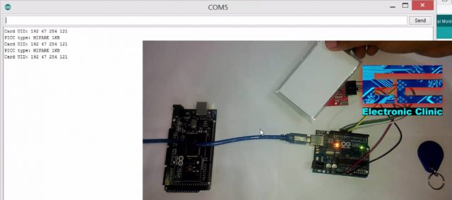
As you can see it successfully read the RFID CARD. I also tested the key chain.
Card identity: 192 47 254 121
Key chain: 00 47 115 137
Now, I have these two Identity numbers which I can use in MFRC522 Arduino codes to control different things. As this is a basic tutorial, so I am not going to make it complicated. Next, I am planning to use both the RFID identity numbers to print some text on the Serial Monitor. Let’s just do it. One more thing, the hardware connections remains exactly the same. You don’t need to change anything. The changes are only on the code side.
MFRC522 RFID Arduino Code:
|
1 2 3 4 5 6 7 8 9 10 11 12 13 14 15 16 17 18 19 20 21 22 23 24 25 26 27 28 29 30 31 32 33 34 35 36 37 38 39 40 41 42 43 44 45 46 47 48 49 50 51 52 53 54 55 56 57 58 59 60 61 62 63 64 65 66 67 68 69 70 71 72 73 74 75 76 77 78 79 80 81 82 83 84 85 86 87 88 89 90 |
/*------------------------ * Pin layout should be as follows: * Signal Pin Pin Pin * Arduino Uno Arduino Mega MFRC522 board * ------------------------------------------------------------ * Reset 9 5 RST * SPI SS 10 53 SDA * SPI MOSI 11 51 MOSI * SPI MISO 12 50 MISO * SPI SCK 13 52 SCK * voltage 3.3v */ #include <SPI.h> #include <MFRC522.h> #define SS_PIN 10 #define RST_PIN 9 int elock = 4; MFRC522 mfrc522(SS_PIN, RST_PIN); // Create MFRC522 instance. void setup() { Serial.begin(9600); // Initialize serial communications with the PC pinMode(elock,OUTPUT); digitalWrite(elock, LOW); SPI.begin(); // Init SPI bus mfrc522.PCD_Init(); // Init MFRC522 card //Serial.println("Scan a MIFARE Classic PICC to demonstrate Value Blocks."); } void loop() { // Prepare key - all keys are set to FFFFFFFFFFFFh at chip delivery from the factory. MFRC522::MIFARE_Key key; for (byte i = 0; i < 6; i++) { key.keyByte[i] = 0xFF; } // Look for new cards if ( ! mfrc522.PICC_IsNewCardPresent()) { return; } // Select one of the cards if ( ! mfrc522.PICC_ReadCardSerial()) { return; } // Now a card is selected. The UID and SAK is in mfrc522.uid. // Dump UID Serial.print("Card UID:"); for (byte i = 0; i < mfrc522.uid.size; i++) { // Serial.print(mfrc522.uid.uidByte[i] < 0x10 ? " 0" : " "); // Serial.print(mfrc522.uid.uidByte[i], DEC); } Serial.println(); // Dump PICC type byte piccType = mfrc522.PICC_GetType(mfrc522.uid.sak); // Serial.print("PICC type: "); //Serial.println(mfrc522.PICC_GetTypeName(piccType)); if ( piccType != MFRC522::PICC_TYPE_MIFARE_MINI && piccType != MFRC522::PICC_TYPE_MIFARE_1K && piccType != MFRC522::PICC_TYPE_MIFARE_4K) { //Serial.println("This sample only works with MIFARE Classic cards."); return; } // defining Cards here if( (mfrc522.uid.uidByte[0] == 192) && (mfrc522.uid.uidByte[1] == 47) && (mfrc522.uid.uidByte[2] == 254) && (mfrc522.uid.uidByte[3] == 121) ) { Serial.println("Card detected"); } else if( (mfrc522.uid.uidByte[0] == 00) && (mfrc522.uid.uidByte[1] == 47) && (mfrc522.uid.uidByte[2] == 115) && (mfrc522.uid.uidByte[3] == 137) ) { Serial.println("Key chain"); } else Serial.println("unregistered user"); delay(1000); } |
Arduino MFRC522 Code Explanation:
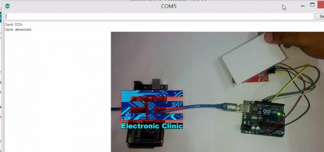
The purpose of this Arduino MFRC522 Code is to print two text messages on the Serial monitor, when the card is detected, it prints “Card Detected” and when the key chain is detected then it prints “Key chain”
if( (mfrc522.uid.uidByte[0] == 192) && (mfrc522.uid.uidByte[1] == 47) && (mfrc522.uid.uidByte[2] == 254) && (mfrc522.uid.uidByte[3] == 121) )
{
Serial.println(“Card detected”);
}
else
if( (mfrc522.uid.uidByte[0] == 00) && (mfrc522.uid.uidByte[1] == 47) && (mfrc522.uid.uidByte[2] == 115) && (mfrc522.uid.uidByte[3] == 137) )
{
Serial.println(“Key chain”);
}
You can clearly see how these two identity numbers are used. You can replace these RFID identity numbers with yours. Anyways, I uploaded the code above and I successfully detected with the RFID Tags.
Then I tested my RFID Key Chain Tag
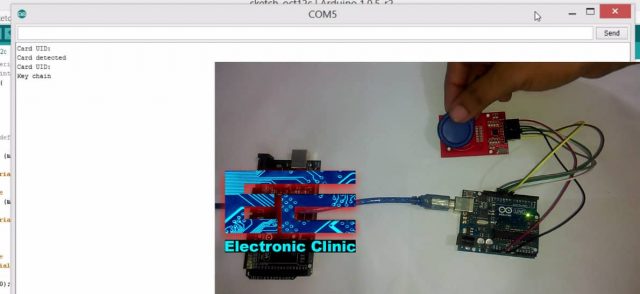
I printed messages on the Serial monitor, but you can modify the code to control the Onboard LED. You can simply turn ON and turn OFF the LED using your RFID tags. So, that’s all for now. If you have any questions, let me know in a comment.
Discover more from Electronic Clinic
Subscribe to get the latest posts sent to your email.


