Nodemcu RFID Firebase, circuit diagram, and programming
Nodemcu RFID Firebase Project Description:
Nodemcu RFID Firebase, circuit diagram, and programming- In this tutorial, you will learn how to interface MFRC522 RFID Module with Nodemcu ESP8266 WiFi module and send the RFID card UID to the Google Firebase Database account. This is an IoT based project, the RFID Tags ids can be monitored from anywhere around the world using the Firebase Database account.
A few days back I posted an article “Arduino Firebase Database, Students Attendance system using RFID and GSM”. In this project, I also used the Arduino with Nodemcu. Later, I decided why not to use only the Nodemcu with RFID and send the RFID tags id numbers to the Firebase account.
I have been using Google Firebase in different projects, I have already explained the very details on how to set up your Google Firebase database account, and then how to use it in IoT related projects.
If you are a beginner and you have never used the Nodemcu ESP8266 WiFi Module, MFRC522 RFID Module, and Google Firebase Database account, then I highly recommend reading my articles given below.
Nodemcu ESP8266 Pinout, Features, and specifications
This tutorial is really important for beginners. In this tutorial, I have explained all the details covering Pinout, Features, and specifications.
Nodemcu ESP8266 Power Supply designing
This tutorial is also very important, after following this tutorial you will be able to design your own regulated power supply for the Nodemcu Module. You will need this power supply for practical implementation.
How to setup Firebase account for Nodemcu
This tutorial is the most important one, as in this tutorial I have explained step by step how to setup up your Google Firebase database account and then how to send the sensors data to the Google Firebase account.
Setup Firebase Account for ESP32
This tutorial is the latest one that I posted a few days ago. You can also follow this tutorial for creating your own Firebase Database account. The firebase account set up for the Nodemcu ESP8266 and the ESP32 are exactly the same.
You need to read the above articles if you want to learn everything like a Pro. After reading the above articles, you will be able to design your own advanced level projects using Nodemcu ESP8266 or ESP32 with the Firebase account.
The components and tools used in this project can be purchased from Amazon, the components Purchase links are given below:
MFRC522 RFID module with tags:
Other Tools and Components:
Super Starter kit for Beginners
PCB small portable drill machines
*Please Note: These are affiliate links. I may make a commission if you buy the components through these links. I would appreciate your support in this way!
MFRC522 RFID Module:
As you can see this is the MFRC522 RFID module. The MFRC522 is a highly integrated reader/writer IC for contactless communication at 13.56 MHz. This module has a total of 8 male headers which are clearly labeled as SDA, SCK, MOSI, MISO, IRQ, GND, RST, and 3.3V. As per the datasheet, the typical voltage is 3.3V while the maximum voltage is 3.6 volts. This module can be easily powered up using the Nodemcu ESP8266 Wifi Module.
MFRC522 RFID Module Pins Description:
- VCC supplies power for the module. This can be anywhere from 2.5 to 3.3 volts. You can connect it to 3.3V output from your Arduino. Remember connecting it to a 5V pin will likely destroy your module!
- RST is an input for Reset and power-down. When this pin goes low, hard power-down is enabled. This turns off all internal current sinks including the oscillator and the input pins are disconnected from the outside world. On the rising edge, the module is reset.
- GND is the Ground Pin and needs to be connected to the GND pin on the Arduino.
- IRQ is an interrupt pin that can alert the microcontroller when the RFID tag comes into its vicinity.
- MISO / SCL / Tx pin acts as Master-In-Slave-Out when the SPI interface is enabled, acts as a serial clock when the I2C interface is enabled and acts as serial data output when UART interface is enabled.
- MOSI (Master Out Slave In) is SPI input to the RC522 module.
- SCK (Serial Clock) accepts clock pulses provided by the SPI bus Master i.e. Arduino.
- SS / SDA / Rx pin acts as Signal input when the SPI interface is enabled, acts as serial data when the I2C interface is enabled and acts as serial data input when the UART interface is enabled. This pin is usually marked by encasing the pin in a square so it can be used as a reference for identifying the other pins.
MFRC522 RFID Reader connection with Nodemcu ESP8266:
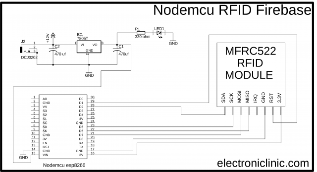
Above is the most basic circuit diagram explaining how the MFRC522 RFID module is interfaced with the Nodemcu module. The above connections are enough to get started with the Nodemcu and RFID module. You can simply power up all the electronics using your computer or laptop. Once you are done with the basic programming then you can follow the circuit diagram given below.
- The 3.3V pin of the MFRC522 RFID module is connected with the 3.3V pin of the Nodemcu module.
- The reset pin of the RFID module is connected with the D1 pin of the Nodemcu ESP8266.
- The IRQ pin of the MFRC522 Module is not connected.
- The MISO pin of the RFID module is connected with the D6 pin of the Nodemcu module.
- The MOSI pin of the RFID reader is connected with the D7 pin of the Nodemcu ESP8266.
- The SCK pin of the RFID module is connected with the D5 pin of the Nodemcu and
- Finally, the SDA pin of the MFRC522 RFID Reader is connected with the D2 pin of the Nodemcu ESP8266 Wifi Module.
Nodemcu RFID Firebase Programming:
|
1 2 3 4 5 6 7 8 9 10 11 12 13 14 15 16 17 18 19 20 21 22 23 24 25 26 27 28 29 30 31 32 33 34 35 36 37 38 39 40 41 42 43 44 45 46 47 48 49 50 51 52 53 54 55 56 57 58 59 60 61 62 63 64 65 66 67 68 69 70 71 72 73 74 75 76 77 78 79 80 81 82 83 84 85 86 87 88 89 90 91 92 93 94 95 96 97 98 99 100 101 102 103 104 105 106 107 108 109 110 111 112 113 114 115 116 117 118 119 120 121 122 123 124 125 126 127 128 129 130 131 132 133 134 135 136 137 138 139 140 141 142 143 144 145 146 147 148 149 150 151 152 153 154 155 156 157 158 159 160 |
// // Copyright 2015 Google Inc. // // Licensed under the Apache License, Version 2.0 (the "License"); // you may not use this file except in compliance with the License. // You may obtain a copy of the License at // // http://www.apache.org/licenses/LICENSE-2.0 // Unless required by applicable law or agreed to in writing, software // distributed under the License is distributed on an "AS IS" BASIS, // WITHOUT WARRANTIES OR CONDITIONS OF ANY KIND, either express or implied. // See the License for the specific language governing permissions and // limitations under the License. // // FirebaseDemo_ESP8266 is a sample that demo the different functions // of the FirebaseArduino API. //https://www.electroniclinic.com/ //Download Libraries #include <ESP8266WiFi.h> #include <FirebaseArduino.h> #include <SPI.h> #include <MFRC522.h> // Set these to run example. #define SS_PIN 4 //D2 #define RST_PIN 5 //D1 #define FIREBASE_HOST "wemos4firebase.firebaseio.com" //https://wemos4firebase.firebaseio.com/ #define FIREBASE_AUTH "XI4tCRr5aPEEbrZZVgDxgkL42NFGbwu4Ds84XYDp" #define WIFI_SSID "PRIMERA_RED" #define WIFI_PASSWORD "Ch1c0n4hu1" MFRC522 mfrc522(SS_PIN, RST_PIN); // Create MFRC522 instance/object. int variable = 0; void setup() { Serial.begin(9600); // Initiate a serial communication SPI.begin(); // Initiate SPI bus mfrc522.PCD_Init(); // Initiate MFRC522 Serial.println("Show your card:"); int n = 0; // connect to wifi. WiFi.begin(WIFI_SSID, WIFI_PASSWORD); Serial.print("connecting"); while (WiFi.status() != WL_CONNECTED) { Serial.print("."); delay(500); } Serial.println(); Serial.print("connected: "); Serial.println(WiFi.localIP()); Firebase.begin(FIREBASE_HOST, FIREBASE_AUTH); } void loop() { // Look for new cards if ( ! mfrc522.PICC_IsNewCardPresent()) { return; } // Select one of the cards if ( ! mfrc522.PICC_ReadCardSerial()) { return; } //Show UID on serial monitor Serial.println(); String content= ""; byte letter; for (byte s = 0; s < mfrc522.uid.size; s++) { //Serial.print(mfrc522.uid.uidByte[s]); //rfid.uid.uidByte[s] // ! mfrc522.PICC_HaltA(); // append a new value to /logs String name = Firebase.pushInt("logs",mfrc522.uid.uidByte[s]); // handle error if (Firebase.failed()) { Serial.print("pushing /logs failed:"); Serial.println(Firebase.error()); return; } //Serial.print("pushed: /logs/(mfrc522.uid.uidByte[s])"); Serial.println(name); } // set value Firebase.setFloat("number", 42.0); // handle error if (Firebase.failed()) { Serial.print("setting /number2 failed:"); Serial.println(Firebase.error()); return; } delay(1000); // update value Firebase.setFloat("number", 43.0); // handle error if (Firebase.failed()) { Serial.print("setting /number1 failed:"); Serial.println(Firebase.error()); return; } delay(1000); // get value Serial.print("number: "); Serial.println(Firebase.getFloat("number")); delay(1000); // remove value Firebase.remove("number"); delay(1000); // set string value Firebase.setString("message", "hello world"); // handle error if (Firebase.failed()) { Serial.print("setting /message failed:"); Serial.println(Firebase.error()); return; } delay(1000); // set bool value Firebase.setBool("truth", false); // handle error if (Firebase.failed()) { Serial.print("setting /truth failed:"); Serial.println(Firebase.error()); return; } delay(1000); // append a new value to /logs String name = Firebase.pushInt("logs", n++); // handle error if (Firebase.failed()) { Serial.print("pushing /logs failed:"); Serial.println(Firebase.error()); return; } Serial.print("pushed: /logs/"); Serial.println(name); delay(1000); } |
Nodemcu RFID Firebase, Final Circuit Diagram:
After, you are done with the basic programming. Finally, you can use this circuit to power up the Nodemcu ESP8266 wifi module. The regulated 5V power supply is based on the LM7805 voltage regulator. J1 is the DC female power jack and this is where we connect the external 12 to 25V power supply. Two 470uf Decoupling capacitors are connected at the input and output sides of the 7805 Regulator. A 330-ohm resistor is connected in series with a 2.5V LED. This is a current limiting resistor.
A wire from the output leg of the 7805 Linear voltage regulator is connected with the VIN pin of the Nodemcu module. Make sure the ground leg of the 7805 voltage regulator is connected with the ground pin of the Nodemcu ESP8266 WiFi Module. The connections of the MFRC522 RFID module with the Nodemcu remain the same.
RFID related projects:
· Arduino RFID Servo Motor Control system for Car Parking “MFRC522”
· RFID & GSM based student Attendance Alert message to parents
· RFID based students attendance system with message Alert
· Bike anti-theft system using MFRC522 RFID module
· Raspberry Pi Home Automation using RC522 RFID, Smart Home


Hi, I tried compiling the code and got an error which says, ‘n’ is not declared. The error is from this line. String name = Firebase.pushInt(“logs”, n++);
I hope you can help me solve this error. Thank you in advance!